Refine
Estimated Years 1930-1939Clear
8,921 results foundRefine Search
American Society of Heating and Ventilating Engineers Guide, 1934 Chapter 24--Gravity Warm Air Systems 7.
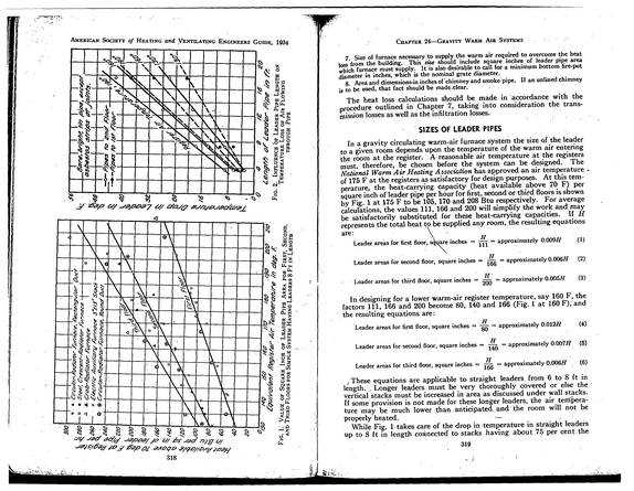
refid# M41N87aQrD6ynKV19O6Y6Rk7a1 page
Special Committees Committee on Admission and Advancement: J.
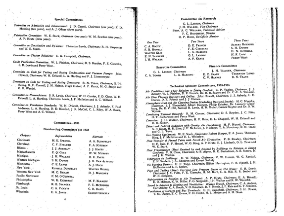
refid# 63EjNyw600pzxXNpDzxL9a9m1 page
'/ American Society of Heating and Ventilating Engineers Guide, 1934 1910 President....................................--... .....Jas.
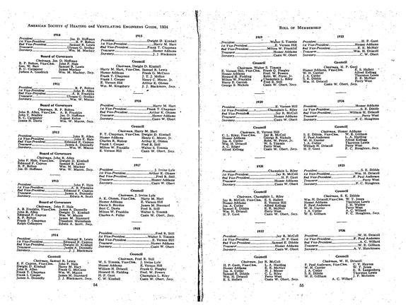
refid# kD56jEeOG8wVXb2okaVZNKXQJ1 page
American.
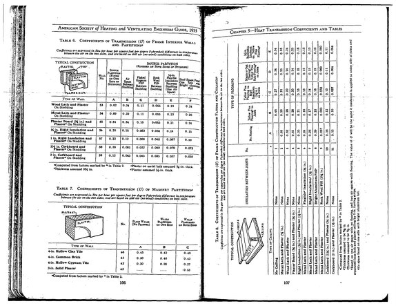
refid# zdVawB2gVM4Nkp42Nr4rQnRQB1 page
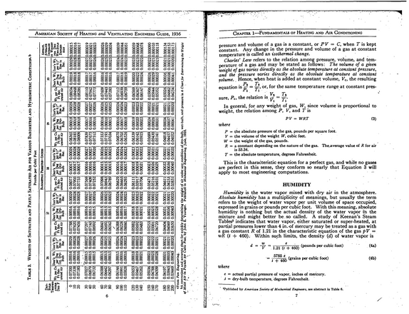
T able 3.
refid# wq9wJ1D38xDz8BoDbML5qyRx41 page
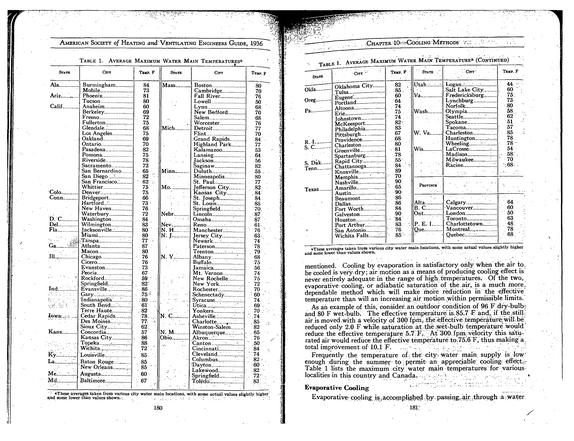
American Society of Heating and Ventilating Engineers Guide, 1936 State Table 1.
refid# 93gdJ9vO2JQNObp2kg1XXXg061 page
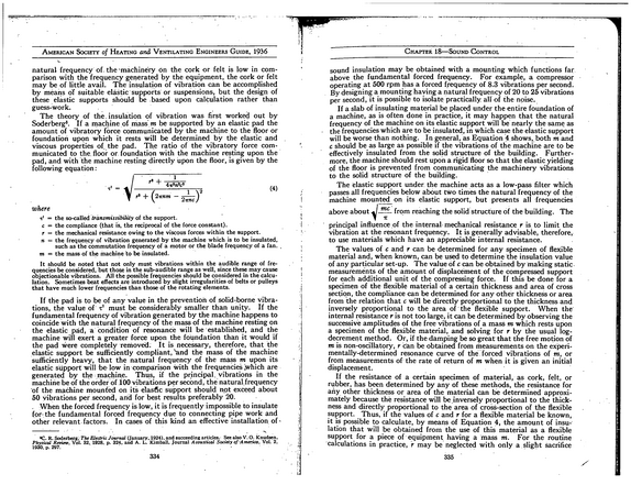
1936American Society of Heating and Ventilating Engineers Guide, natural frequency of. the 'machinery on the cork or felt is low in com parison with the frequency generated by the equipment, the cork or felt may be of little avail.
refid# N28J1pwGEGQ1xpBJGODz5jyb1 page
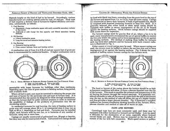
American Society of Heating and Ventilating Engineers Guide, 1936 depends largely on the kind of fuel to be burned.
refid# GmnGxDg5Dn8YbZKNR5moykydv1 page
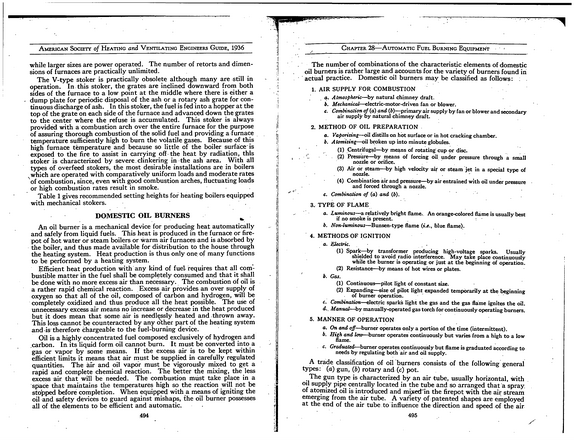
of andAmerican Society Heating Ventilating Engineers Guide, 1936 while larger sizes are power operated.
refid# KR8K6R7G8oEKB3DN9pB0JrpDr1 page
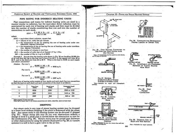
American Society of Heating and Ventilating Engineers Guide, 1936 PIPE SIZING FOR INDIRECT HEATING UNITS Pipe connections and mains for indirect heating units are sized in a manner similar to radiators, but the equivalent direct radiation must be ascertained for each row of heating unit stacks and then must be divided into the number of stacks constituting that row and into the number of connections to each stack.
refid# 1519BJEJ2Ya96LoEjJ0Q6ZmYZ1 page
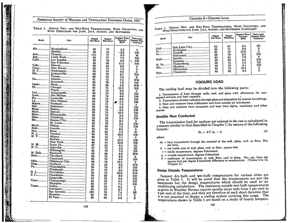
American Society of Heating and Ventilating Engineers Guide, 1937~~~ Table 1.
refid# zbpdaxzgombvYkwv2aV4neBe71 page
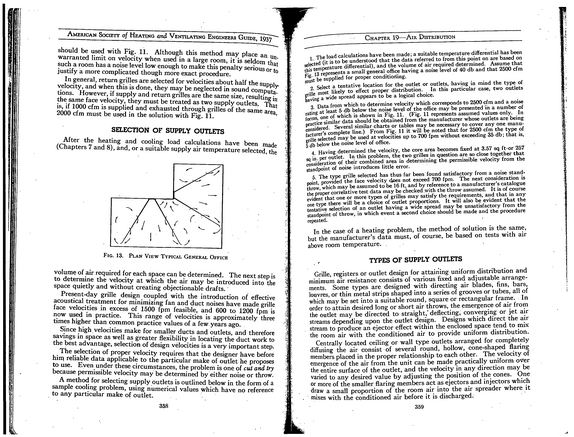
American Society of Heating and Ventilating Engineers Guide, 1937~~~ should be used with Fig. 11.
refid# Ozmvna0KmN3OoMvvz71rMegoX1 page
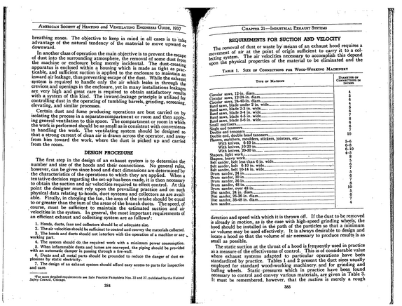
American Society of Heating and Ventilating Engineers Guide, 1937 breathing zones.
refid# D0q2xYvq2XYGjKvXznbLO6L51 page
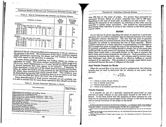
American Society of Heating and Ventilating Engineers Guide, 1937 Table 2..
refid# wDJ7xpmYmgLVa14ERezJEVRyd1 page
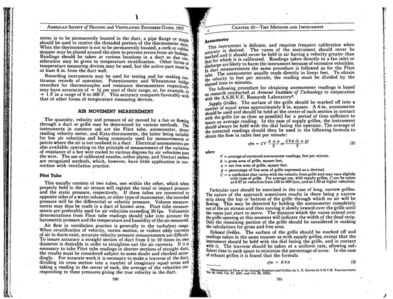
American Society of Heating and Ventilating Engineers Guide, 1937 Chapter 43--Test Methods and Instruments meter is to be permanently located in the duct, a pipe flange or nipDi should be used to receive the threaded portion of the thermometer stem* When the thermometer is not to be permanently located, a cork or rubbe stopper may be placed around the stem to prevent.errors from air leakage Readings should be taken at various locations in a duct so due con' sideration may be given to temperature stratification.
refid# 6w85G8oG6Zk9GggNRM81DeBb41 page