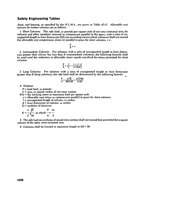
Safety Engineering Tables shear, and bearing, as specified by the NLM A, are given in Table 47-C Allowable unit stresses for timber columns are as follows 1 Short Columns The safe load, in pounds per square inch of net cross-sectional area, for columns and other members stressed in compression parallel to the gram, with a ratio of un supported length to least dimension (Hd) not exceeding eleven (short columns) shall not exceed the allowable unit compression stress (c) parallel to grain for short columns, t e , P A=c 2 Intermediate Columns For columns with a ratio of unsupported length to least dimen sion greater than eleven but less than K (intermediate columns), the following formula shall be used until the reduction in allowable stress equals one-third the stress permitted for short columns 3 Long Columns For columns with a ratio of unsupported length to least dimension greater than K (long columns), the safe load shall be determined by the following formula P 7T*E 0 274E A 36(1/dy (l/dy 4 Notation P = total load, m pounds A = area, m square inches of net cross section P/A = the working stress or maximum load per square inch c = allowable unit stress in compression parallel to grain for short columns 1 = unsupported length of column, m inches d = least dimension of column, m inches E = modulus of elasticity P 2c at which -- = -- A3 5 The safe load on a column of round cross section shall not exceed that permitted for a square column of the same cross-sectional area 6 Columns shall be limited m maximum length to 1/d = 50 1576
refid# evQBjrb62OjQJr95jGnGZz5Ep1 page
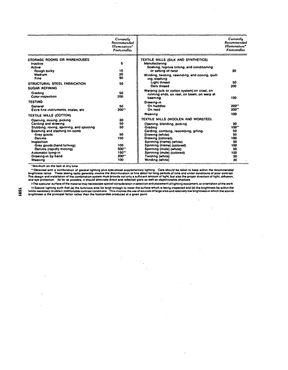
Currently Recommended Illumination* Footcandles Currently Recommended Illumination Footcandles STORAGE ROOMS OR WAREHOUSES Inactive Active Rough bulky Medium Fine STRUCTURAL STEEL FABRICATION SUGAR REFINING Grading Color inspection TESTING General Extra fine instruments, scales, etc TEXTILE MILLS (COTTON) Opening, mixing, picking Carding and drawing Slubbing, roving, spinning, and spooling Beaming and slashing on comb Grey goods Denims Inspection Grey goods (hand turning) Denims (rapidly moving) Automatic tying-in Drawing-in by hand Weaving 5 10 20 50 50 50 200 50 200" 30 50 50 50 150 100 500" 150" 200" 100 TEXTILE MILLS (SILK AND SYNTHETICS) Manufacturing Soaking, fugitive tinting, and conditioning or setting of twist Winding, twisting, rewinding, and coning, quill* mg, slashing Light thread Dark thread Warping (silk or cotton system) on creel, on running ends, on reel, on beam, on warp at beaming Drawing-in On heddles On reed Weaving TEXTILE MILLS (WOOLEN AND WORSTED) Opening, blending, picking Grading Carding, combing, recombing, gillmg Orawing (white) Drawing (colored) Spinning (frame) (white) Spinning (frame) (colored) Spinning (mule) (white) Spinning (mule) (colored) Twisting (white) Winding (white) 30 50 200 100 200" 200" 100 30 100" 50 50 100 50 100 50 100 50 30 Minimum on the task at any lime "Obtained with a combination of general lighting plus specialized supplementary lighting Care should be taken to keep within the recommended brightness ratios These seeing tasks generally involve the discnmination of fine detail tor long periods of time and under conditions of poor contrast The design and installation of the combination system must provide not only a sufficient amount of light, but also the proper direction of light, diffusion, and eye protection As far as possible, it should eliminate direct and reflected glare as well as objectionable shadows tThe specular surface of the matenal may necessitate special consideration in selection and placement of lighting equipment, or onentation of the work ft Special lighting such that (a) the luminous area be large enough to cover the surface which is being inspected and (b) the bnghtness be within the limits necessary to obtain comfortable contrast conditions This involves the use of sources of large area and relatively low bnghtness in which the source brightness is the principal factor rather than the footcandles produced at a given point 1591
refid# ExaJGGBdvQOoO0M99QQ6qp7aL1 page
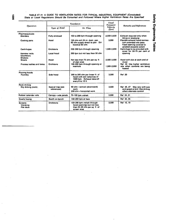
Safety Engineering Tables 1596 TABLE 47-H A GUIDE TO VENTILATION RATES FOR TYPICAL INDUSTRIAL EQUIPMENT (Concluded) State or Local Regulations Should Be Consulted and Followed Where Higher Ventilation Rates Are Specified Operation Pharmaceuticals Blenders Coating pans Centnfuges Hammer mills Oscillators Shakers Mixers Process kettles and tanks Pouring hoods Foundry Rock drilling Dry dnllmg (rock).
refid# qMX2oanE18LNyrK9byGyB5Zk1 page
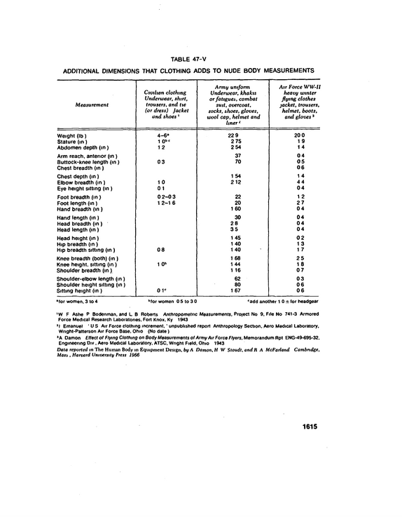
TABLE 47-V ADDITIONAL DIMENSIONS THAT CLOTHING ADDS TO NUDE BODY MEASUREMENTS Measurement Civilian clothing Underwear, shtrt, trousers, and tie (or dress) Jacket and shoes 1 Army uniform Underwear, khakis orfatigues, combat suit, overcoat, socks, shoes, gloves, wool cap, helmet and liner1 Air Force WW-II heavy winter flying clothes jacket, trousers, helmet, boots, and gloves 3 Weight (lb) Stature (in) Abdomen depth (in) Arm reach, anterior (in ) Buttock-knee length (in) Chest breadth (in) Chest depth (in) Elbow breadth (in) Eye height sitting (in ) Foot breadth (in) Foot length (in) Hand breadth (in) Hand length (in) Head breadth (in) Head length (in) Head height (in) Hip breadth (in) Hip breadth sitting (in ) Knee breadth (both) (in ) Knee height, sitting (in) Shoulder breadth (in) Shoulder-elbow length (in) Shoulder height sitting (in ) Sitting height (in ) `for women, 3 to 4 4-6" 1 0bc 12 03 10 01 0 2-0 3 1 2-1 6 08 1 0b 01* "for women 0 5 to 3 0 22 9 2 75 254 37 70 1 54 212 22 20 1 60 30 28 35 1 45 1 40 1 40 1 68 1 44 1 16 62 80 1 67 20 0 19 14 04 05 06 14 44 04 12 27 04 04 04 04 02 13 17 25 18 07 03 06 06 'add another 1 0 . for headgear W F Ashe P Bodenman. and L.
refid# LJbBNrY5nJVnz05px1Z33mbvb1 page
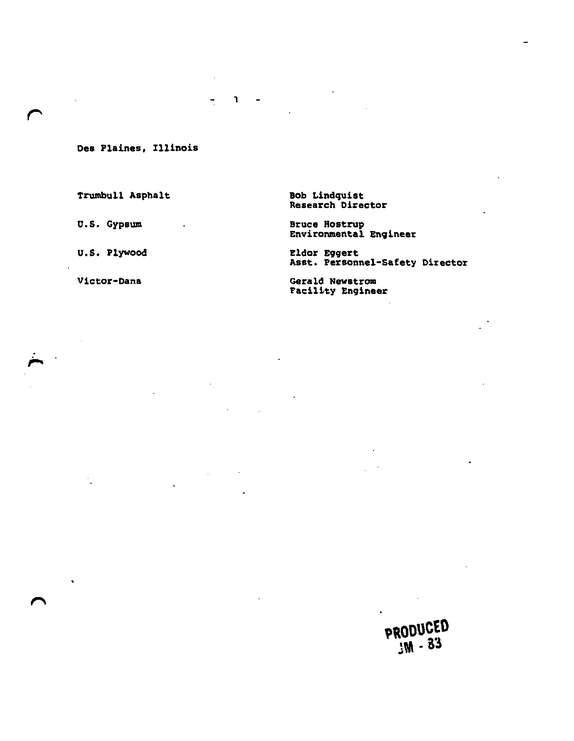
Des Plaines, Illinois Trumbull Asphalt U.S.
refid# JN6B8vMM8x1Nn6b98k9GNdJvv1 page
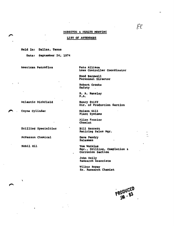
ASBESTOS 6 HEALTH MEETING LIST OF ATTENDEES Held In: Dallas* Texas Date: September 24* 1974 American Petrofina Atlantic Richfield Coyne Cylinder Drilling Specialties McKesson Chemical Mobil Oil Pete Allison Loss Controller Coordinator Hood Barnwell Personnel Director Robert Crooks Safety R.
refid# 93grr4Vkwkb8Eyq7xOaX6621L1 page
U.
refid# qv7wk9pyB2d0X5Rgn3bjQ1Zq1 page
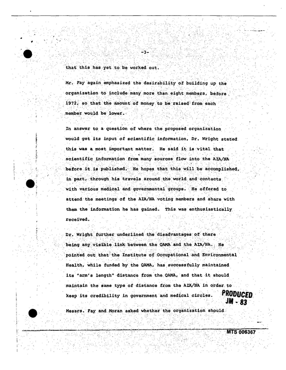
$ | ' \ that this has yet to be worked out.
refid# DM1o111VQ2dpnmw4vNXzRgr0n1 page
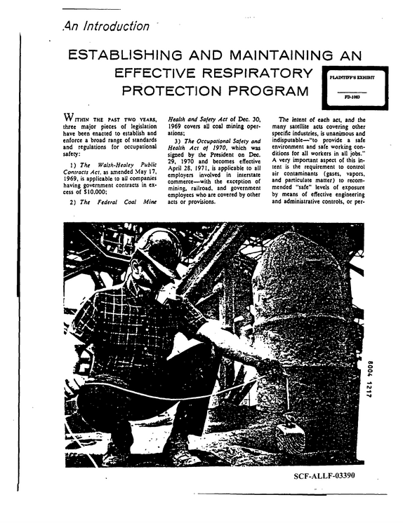
An Introduction ESTABLISHING AND MAINTAINING AN EFFECTIVE RESPIRATORY PROTECTION PROGRAM W ITHIN THE PAST TWO YEARS, three major pieces of legislation have been enacted to establish and enforce a broad range of standards and regulations for occupational safety: 1) The Walsh-Healey Public Contacts Act. as amended May 17, 1969, is applicable to all companies having government contracts in ex cess of $10,000; 2) The Federal Coal Mine Health and Safety Act of Dec. 30, 1969 covers all coal mining oper ations; 3) The Occupational Safety and Health Act of 1970, which was signed by the President on Dec. 29, 1970 and becomes effective April 28, 1971, is applicable to all employers involved in interstate commerce--with the exception of mining, railroad, and government employees who are covered by other acts or provisions.
refid# Yj06qgp5aR6n0QMBYBZQRLk9n1 page
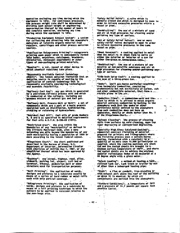
operation excluding any tine during which the -equipment Is idle.. for continuous processes.
refid# 1gV4RJgvpy88dMwdpRrrbxz8Z1 page
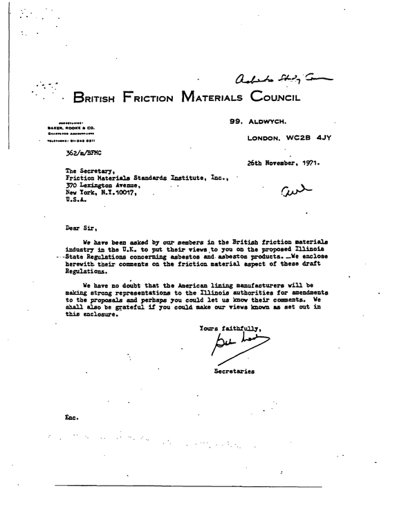
British Friction Materials Council IARIR.
refid# KJ6GGG96w8Nb5gGvOGRmZgxN61 page
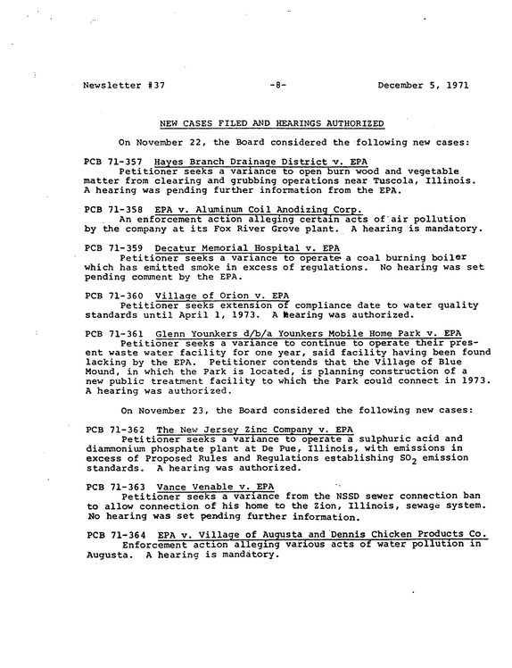
Newsletter #37 8- - December 5, 1971 NEW CASES FILED AND HEARINGS AUTHORIZED On November 22, the Board considered the following new cases: PCB 71-357 Hayes Branch Drainage District v.
refid# Ed3LxN7QBw2oeE0K5x3epBM2V1 page
START, COPY BOX NO.
refid# 1gBwnjMaZJVYedM71wx688y2m1 page
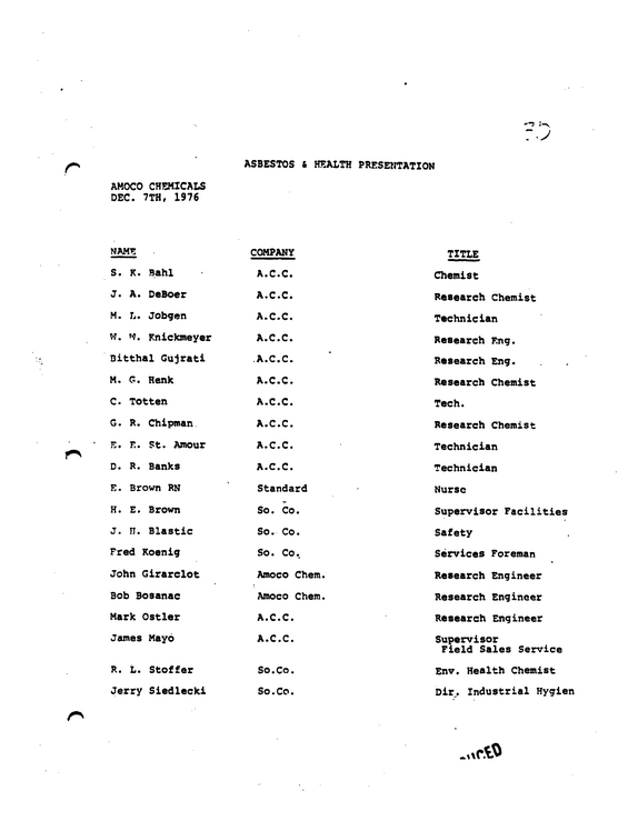
AMOCO CHEMICALS DEC. 7TH, 1976 ASBESTOS & HEALTH PRESENTATION NAME S.
refid# M424GZjo9N5LNJj8k9dbK3mYy1 page
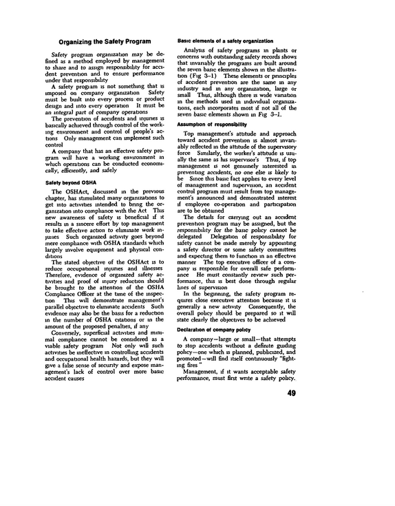
Organizing the Safety Program Safety program organization may be de fined as a method employed by management to share and to assign responsibility for acci dent prevention and to ensure performance under that responsibility A safety progiam is not something that is imposed on company organization Safety must be built into every process or product design and into every operation It must be an integral part of company operations The prevention of accidents and injuries is basically achieved through control of the work ing environment and control of people's ac tions Only management can implement such control A company that has an effective safety pro gram will have a working environment m which operations can be conducted economi cally, efficiently, and safely Safety beyond OSHA The OSHAct, discussed in the previous chapter, has stimulated many organizations to get into activities intended to bring the or ganization into compliance with the Act This new awareness of safety is beneficial if it results in a sincere effort by top management to take effective action to eliminate work mjunes Such organized activity goes beyond mere compliance with OSHA standards which largely mvolve equipment and physical con ditions The stated objective of the OSHAct is to reduce occupational injuries and illnesses Therefore, evidence of organized safety ac tivities and proof of injury reduction should be brought to the attention of the OSHA Compliance Officer at the time of the inspec tion This will demonstrate management's parallel objective to eliminate accidents Such evidence may also be the basis for a reduction in the number of OSHA citations or in the amount of the proposed jpenalbes, if any Conversely, superficial activities and mini mal compliance cannot be considered as a viable safety program Not only will such activities be ineffective in controlling accidents and occupational health hazards, but they will give a false sense of security and expose man agement's lack of control over more basic accident causes Basic elements of a safety organization Analysis of safety programs in plants or concerns with outstanding safety records shows that invariably the programs are built around the seven basic elements shown in the illustra tion (Fig 3-1) These elements or principles of accident prevention are the same m any industry and in any organization, large or small Thus, although there is wide variation in the methods used m individual organiza tions, each mcoiporates most if not all of the seven basic elements shown in Fig 3--1.
refid# KJmm5OqOyxjbgV7jEeZ5a2ngw1 page