Refine
Estimated Years UndatedClear
92,592 results foundRefine Search
The workmen should see that jacks are well lubricated, but only at points where lubrica tion is specified, and should inspect them for broken teeth or faulty holding fixtures A jack should never be thrown or dropped upon the floor, such treatment may crack or distort the metal, thus causing the jack to break when a load is lifted It is important that the floor or ground sur face upon which the jack is placed be level and clean, and that the safe limit of floor load ing is not exceeded If the surface is earth, the jack base should be set on substantial heavy wood blocking, preferably hardwood, of sufficient size that the blocking will not turn over, shift, or sink If the surface is not perfectly level, the jack may be set on block ing, which should be leveled by substantial shims or wedges securely placed so that they cannot be crushed or forced out of place To prevent the load from slipping, no metalto-metal contact should be permitted be tween the jack head and the load A wood shim, preferably hardwood and longer and wider than the face of the jack head, should be placed between the jack head and the con tact surface of the load One-inch wood stock is suitable for this purpose (Fig 19-6) "Extenders" of wood or metal, intended to provide a higher nse where a jack cannot reach up to the load nor lift it high enough, should never be used Instead, a larger jack should be obtained or higher blocking--which is correspondingly wider and longer-- should be placed under the jack All lifts should be vertical with the jack cor rectly centered for the lift, the base on a per fectly level surface, and the head with its shim bearing against a perfectly level meeting surface When an emergency requires that the lifting force be applied at an angle, extra precautions must be taken which include 1 A base of blocking securely fastened to gether and to the ground to make an im movable surface at right angles to the lift for the jack base to rest on 2 Cleats on the blocking to prevent shifting of the jack base 3 A meeting surface at nght angles to the di rection of the lift for the jack head with its shim to bear against 4 Props or guys to the load to prevent its swinging sidewise when lifting begins When a jack handle is placed in the socket, the workman should make sure that the area is clear and that there is ample room for an unobstructed swing of the handle before he applies pressure A faulty movement m the load may cause the handle to pop up and strike another worker The man operating the handle should stand to one side so that if the handle kicks, it will not catch him m the body or face After the load is raised, metal horses or substantial heavy wooden horses or blocking should be placed under it for support m case the jack should let go A raised load should never be allowed to remain supported only by jacks The handles of the jacks should be removed and placed out of the way to prevent workers from walking into them When a jack is released, the worker should keep all parts of his body clear of the move ment of the handle A hydraulic jack which leaks oil should be taken out of service and repaired Hydraulic jacks may settle after raising a load It is, therefore, especially important to place block ing under a load that has been raised by such jacks Screw jacks have a tendency to twist when a heavy load causes the floating head of the jack to bind The base of a screw jack should be anchored as securely as possible so that the jack base will not twist and slip out from under the load when force is applied on the bars to raise the screw To raise a large piece of equipment with screw jacks, two or more jacks should be used The load should be equally distributed on each jack The jacks should be raised each a little at a time to keep the load level and the strain equal on each screw jack head Workmen using jacks should wear safety shoes and instep-guard protection because jack handles may slip and fall or parts of ma chinery or equipment may come loose and drop as the load is being lifted or shifted Waste or other wiping material should be fur nished to jack operators who should use it to remove oil from their hands and from the jack handles so that they will always have a firm gnp Oil that has collected in the bases of equip ment or machines to be jacked should be removed before the operation is begun to pre vent spillage when the equipment or ma- 511
refid# LJGEN0yapQkQ1V1eNYnXRBn971 page
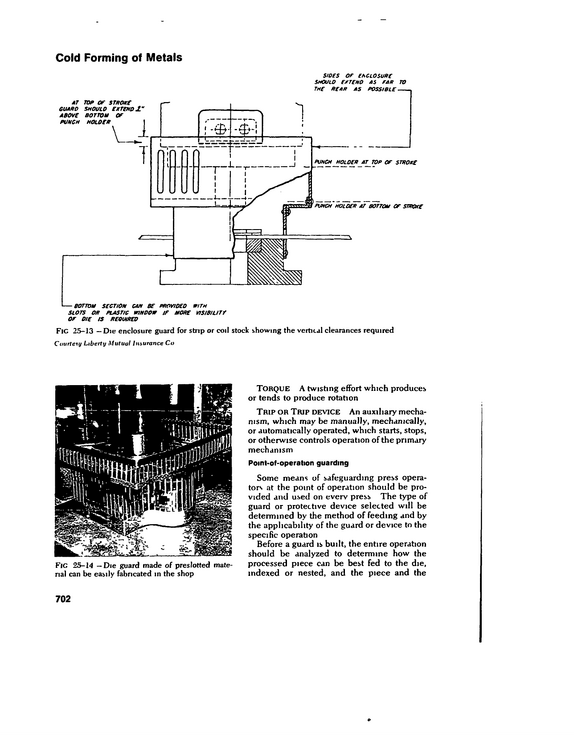
Cold Forming of Metals sides of enclosure should extend as far to SLOTS OR PLASTIC WINDOW IT MORE VISIBIUT/ OF DIE IS REQUIRED FlC 25-13 -- Die enclosure guard for strip or coil stock showing the vertical clearances required Courtery Liberty Mutual Insurance Co FlC 25-14 --Die guard made of preslotted mate rial can be easily fabricated in the shop Torque A twisting effort which produces or tends to produce rotation Trip or Trip device An auxiliary mecha nism, which may be manually, mechanically, or automatically operated, which starts, stops, or otherwise controls operation of the primary mechanism Point-of-operation guarding Some means of safeguarding press opera tors at the point of operation should be pro vided and used on every press The type of guard or protective device selected will be determined by the method of feeding and by the applicability of the guard or device to the specific operation Before a guard is built, the entire operation should be analyzed to determine how the processed piece can be best fed to the die, indexed or nested, and the piece and the 702
refid# eE7gz7VLGRQZ7LJ4XKe0Ek8y1 page
Cold Forming of Metals Air friction clutch presses On a press with air friction clutch/brake, the control performs the following functions 1 Provides that the press operator must hold both run buttons during the down stroke until the slide has descended to a point where there is no longer a hazard Re lease of any button during "holding time" should stop the slide 2 Allows the operator to release buttons after completion of "holding time" and press will complete stroke 3 On "single cycle" operation, it stops the slide at end of a stroke even though op erator holds control buttons depressed 4 Actuates clutch/brake air valve(s) so that friction brake will stop machine at top of stroke 5 Provides anti-repeat protection and pre vents repeat operation with any buttons tied down Starters for main drive motor should be the magnetic, reversing type This feature per mits backing up of the press m the event of a jam without the need for an electrician to change wiring Selector switches should re quire keys so that backing up can be done by authorized personnel only The clutch control should be provided with a main drive motor "forward interlock" so that the press can be run only when the motor is turning m the forward direction "Back ward" operation of the press is unsafe be cause there is no run button "holding time " This interlock also prevents "run" actuation of the clutch air valve before the motor is started or when the flywheel is coasting Starting the motor with the clutch engaged is unsafe since it may result m unexpected downward movement of the slide Inch or jog operation should normally bypass the interlock to allow power-off "inching ' Pressure switches should be provided on the compressed air system downstream from pressure regulators and shut-off valves to as sure that air is present for proper actuation of clutch-brake mechanisms and counterbal ance cylinders These switches should be normally open and wired in senes into the control circuit ahead of the main-dnve-motor starter and clutch/brake control 1 The clutch pressure switch assures that the correct air pressure is available before the machine is started This assures proper movement of the slide and protects clutch plates from excessive wear resulting from slippage 2 The counterbalance pressure switch pre vents a sudden drop of the slide dunng the instant between release of the brake and engagement of the clutch Proper counter balance pressure is also required for quick stopping of the slide dunng the downstroke, or prevention of drop back if the slide is stopped dunng the up stroke Jogging or inching of the slide is often re quired when setting up or trying out dies The use of two-hand inch buttons is preferred for these operations so that both hands must be out of the danger area Where a single button is used, it should be guarded so that it cannot be operated unintentionally The clutch/brake solenoid valve(s) should not be energized directly across the line through the contacts of a single relay, in such a way that faulty operation of this single relay will result in unintended energization of the valve(s) Protection can be accomplished through the use of multiple relays and/or energization of the valve(s) through push but ton switches and rotary limit switches The previous paragraph makes stopping a machine independent of operation of the valve or run relay Normally closed contacts of this relay should be incorporated into the circuit to check actual dropout of the relay The use of a multiple clutch control valve is recommended This is a relatively inex pensive means for reducing the possibility of press repeats due to malfunctioning of a single valve Press clutch control circuits can be either of two types 1 Grounded. with all coils connected to one side of the isolated secondary of a control transformer, and this side grounded to the machine frame, or 2 Ungrounded (double ended) with ground detector lights connected to each side of the line and a double break arrangement On multiple operator presses, complete operating stations not required should be 728
refid# OnD4pxzwxmbL1pJyZeE4GJoj1 page
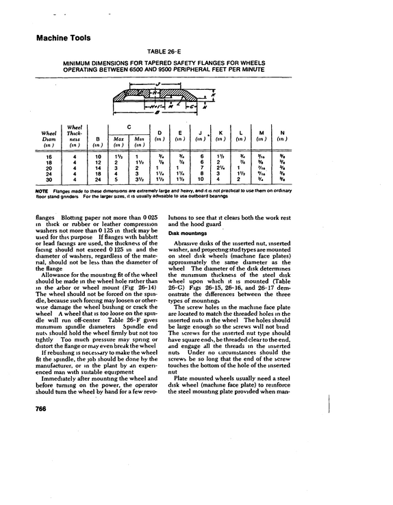
Machine Tools TABLE 26-E MINIMUM DIMENSIONS FOR TAPERED SAFETY FLANGES FOR WHEELS OPERATING BETWEEN 6500 AND 9500 PERIPHERAL FEET PER MINUTE Wheel Diam (in) Wheel Thick ness (in ) B (in) C Max On) Mm (in ) D (in) E (in ) J.
refid# 3JMbEq4Ybpn8d5n3o3v3DoKOx1 page
Hot Working of Metals mg area The scale guard should be moved back, and accumulated scale that would in terfere with safe footing should be removed Forgings should be moved away from the unit immediately and sent to the next work station If another set of forging equipment has been delivered, it should be placed nearby but not direcdy in the area where the ham mer crew will work Service personnel, such as truckers, crane men, and hookers, should be familiar with the proper procedure so that unnecessary handling can be elimi nated The hammer's main power switch or con trol must be shut off and locked before the die keys are loosened The top key is gen erally loosened first, usually with a mounted pneumatic ram (Fig 28-18) A light, well balanced ram suspended from a cross beam or from an overhead crane or chain fall can also be used successfully Using a manually held drift pin or a knock out on a die key after it has been loosened and driven to a position even with the face of the ram or the sow block is a hazardous operation A special type of adjustable knockout (Fig 28-23) that is held in position mechanically rather than manually should be used After the die keys have been driven out, the ram should be raised and propped at once The prop must be m good condition and must be placed on a clean surface On a gravity drop hammer, a jack should be used and a special prop may be required No attempt should be made to raise the hammer to propping level if the top die has a tendency to "hang " The die should be freed first within the shortest possible dis tance from the face of the bottom die The ram on an air drop hammer should be propped with special care After the prop is posi tioned securely under the ram, the power should be shut offand locked out Dies can be removed from the hammer by means of special die chains suspended from an overhead crane or chain fall Special platform trucks with winches are also em ployed for this operation They are practical and safe because the dies are winched out or pulled out horizontally directly onto the table of the truck Dumping the dies out of the hammer onto the floor should not be permitted After the dies have been removed from the hammer, the dowels must be extracted It is important that the two men who drive out the dowels have proper tools, usually a drift and a sledge These tools should be in good condition and have sound handles Because there is metal-to-metal contact, the men must be extremely careful After being removed, dies should be loaded on low steel pallets and taken from the vicinity as soon as possible If dies need repair or modification, the hammer man should notify his foreman The foreman can then send this information to the die servicing department so that the condition can be remedied before the next run Design of dies Hammer dies are usually made of chrome, nickel, or molybdenum stellitem--materials which have high resistance to heat, shock, and abrasion Die blocks are supplied com mercially m four different hardnesses Selecbon of the proper die steel m the correct range of hardness is of utmost importance in controlling checking and breakage of dies Size, amount of striking surface, and height are all pertinent factors m the safe design of dies The correct amount of striking surface must-be allowed in relation to the size of the die Too little striking surface may cause breakage or an undersized forging when the dies pound down Too much striking surface, especially if it is unbalanced, may cause a pull or misalignment Correct die height must be specified, es pecially for resinking forge dies Normal work level should be maintained for the benefit of the hammer man, and the height should never be below a specified minimum, to prevent the bottom of the cylinder from being knocked out Maximum and minimum operating heights should be labeled on each unit for use by the design engineer The dies must be made so that they meet in precise alignment Layout of the dies should provide for the major portion of the heavy forge work to be done m the center of the die under the center of the ram, where the maximum hammer force is transmitted Each impression m the die must be backed up with enough die material to reduce the 842
refid# dQ7QQva7d55gj9ZXaD5z6zOMR1 page
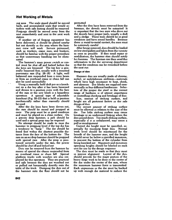
Hot Working of Metals 5IEAM HAMMS MAINTENANCE CHECK Dot*Hammer Nolocation__________________________ REM CHECKS CONDITION TYPE OP EST HIS REPAIR TO REPAS CYl HEAD 601TS MOTION VALVE STEM MOTION VALVE CKANX MOTION VALVE CONNECT WIPES BAB 4 CRANK THIOTTU CRANK THROTTLE LINKAGE RAM 4 SOW BLOCK DIE KEYS 4 SHIMS SOW BLOCK KITS 4 SHIMS GUIDE BOLTS GUIDE WEAR GUU)E ADJUSTING BOLTS GUIDE WEDGE POSITION HOUSING BOLTS 4 SPRINGS TREADLE TtS PLATE LINES PISTON ROD GLAND PLATE GLAND BOLTS TREADLE PLATFORM STEAM CUSHION UNE SCALE HOSE SAFETY LINER SAFETY PROP STEAM LINES STEAM SHUTOFF VALVES REACH ROD COLUMNS FIAT ON BASE COLUMN WEDGE 4 BOLTS SPOOL BOLT 4 PIN SAFETY CABLES CRACKS IN BASE remarks FlG 28-25 (left) -- Maintenance checklist for steam hammers Frequent periodic inspection of every forg ing hammer will help ensure proper condi tion of all bolts, screws, keys, valves, and other parts which may be loosened by vibra tion Similarly, thorough periodic inspec tion and adjustment should be made of all parts of the treadle or pedal, clutch, and other operating mechanisms Worn 01 loose treadle linkage, motion arm, crank arm, and treadle can cause the hammer to go out of control These parts especially should be kept in good repair The clutch is a vital part of the forging press and must be kept in good condition if the press is to operate satisfactorily A broken spring or part which shows wear should be replaced at once Lead casts Lead casts are taken m practically every conceivable manner in the forging industry Casts should be taken only in an isolated area, if possible, where there is no likeli hood of interference from or injury to other workers The die impressions should be dry since hot metal that contacts water produces flying particles of molten metal Lead pots should be ventilated to the out side of the building Forging Upsetters A plant work schedule for repairs may be set up on the basts of the data recorded on the checklists The data may be transferred to the permanent records of the equipment and used for future planning in the maintenance program as well as for comparison of costs In commercial forge plants, steam ham mers constitute a considerable portion of the forging equipment Many hammers are not kept m as efficient condition as possible, usually because management fails to realize that operating and upkeep costs are higher for units in poor condition Waste of steam usually results from worn piston rings or sleeves, loose heads, blown head gaskets, and leaky glands Replacement of wom nngs is good econ omy Worn piston sleeves and sloppy link age make the hammer hard to control and create a hazard Loose cylinder heads also are dangerous The upsetter is a horizontal forging ma chine which forges hot bar stock, usually round, into a great many forms by a squeez ing action instead of impact blows, as m the case of forging hammers Although numer ous hazards are involved m the operation of an upsetter, the most serious problems are encountered in changing the dies The entire machine should be completely enclosed, except for the feed area Heavy wire mesh or expanded or sheet metal rein forced with structural steel should be used Doors may be cut into the enclosure for ser vicing flywheel, brake, and other moving parts A guard should be installed over the operating pedal Safe operating conditions call for the area around the machine to be clean and clear of obstructions and litter It is especially im portant that the top of the machine be clear of any objects, such as loose bolts, bars, nuts, or shims, which might fall into it or from it 844
refid# dQdg6bYERkw2eyvZbj2Ej68J51 page
Hot Working of Metals cuit so that the motor cannot be started when the props are in use All die clamps, bolts, washers, blocking, wrenches, and handling equipment should be m good condition at all times The table wedges which are used for mak ing vertical adjustment of the dies must be kept free of scale so that the wedge can be raised and lowered with minimum pressure Trucks or driving rams should not be used for this operation If wedges are kept free of scale, they can be raised or lowered by hand or by air motor wrench Maintenance Maintenance of forging presses requires the same precautions used in maintenance work on power presses used in cold stamping The operating power source should be locked out so that the equipment cannot be energized while it is being worked on If adjustments have to be made while the press is energized, the work must be earned out under the direct supervision of the maintenance supervisor Suitable permanent work platforms should be installed for making brake adjustments and doing repair work at the surge tank and booster cylinders To prevent falls, mainte nance men should not use portable straight ladders nor stand on parts of the press, such as the press crown or the backshaft Major repair work on forging presses usually requires removal of bulky, heavy parts Tear ing down of the rolling type clutch, flywheel, ram, pitman, and crankshaft requires special heavy-duty rigging used by skilled workmen trained in this type of work The brake should be adjusted properly and kept in good repair Precautions must be taken to prevent the brake lining from be coming flooded with oil A sheet steel disk about 2 in larger than the brake wheel, placed on the eccentric shaft back of the brake wheel, will help reduce the amount of lubricant on the brake Pitman bolts should be securely tightened It may be necessary to design and make a socket or box end wrench with a strong heavy handle for the specific press Flywheel hubs, clutch spline hubs, pinion gears, and brake wheels should not be per mitted to become loose on the pinion shaft If they do become loose and run that way very long, keys and keyways will be ruined and the keys will break out a portion of the pinion shaft on one side of the keyway The keys on each side of the pinion shaft should be inspected periodically and driven tight if they are loose When a key will no longer stay tight, it should be replaced with a carefully fitted new key When the hub or gear on the shaft becomes too loose, it wiil be impossible to hold the keys tight and the shaft will have to be turned down The inside of a steel hub should be welded and bored to a shrink fit on the new shaft size The keyways should be remachmed and new keys made If the hub is cast iron, a tapered sleeve can be made or a new hub fitted to the shaft Expenenced repairmen warn against weld ing the flywheel end of the pinion shaft If normalizing of the welded section is not com plete, a crack may start and allow the shaft to break and drop the rotating flywheel Crank shafts and backshafts on forging presses like wise should not be welded The friction slip on a press should be tight ened so that it will not creep even on heavy jobs If the friction slip is allowed to move a small amount with every forging, this move ment will polish or glaze the friction surfaces and soon the friction slip will move more with each forging This movement will cause the friction surface to score the hub and clamp surfaces Rotation of the flywheel on the friction hub will frequently wear or cut the inside diam eter of the flywheel so that it runs off center To correct this condition, the inside diameter of the flywheel can be bored and fitted with a bronze bushing Sometimes the eccentric shaft becomes cracked in the fillet on each side of the ec centric This defect is usually noticed when the shaft is taken out so that the mam bearings can be checked or the shaft can be machined This crack should be examined carefully to determine its length, depth, and direction of travel If the crack is in a critical area where failure would permit the rolling dutch to drop oft, then the shaft must be replaced Other Forging Equipment Hot trimming dies can be made from hard ened chrome, nickel, carbon and vanadium steels or from medium carbon steels with 848
refid# zzRdOXb9qO2G0gNK8aNRBrNK71 page
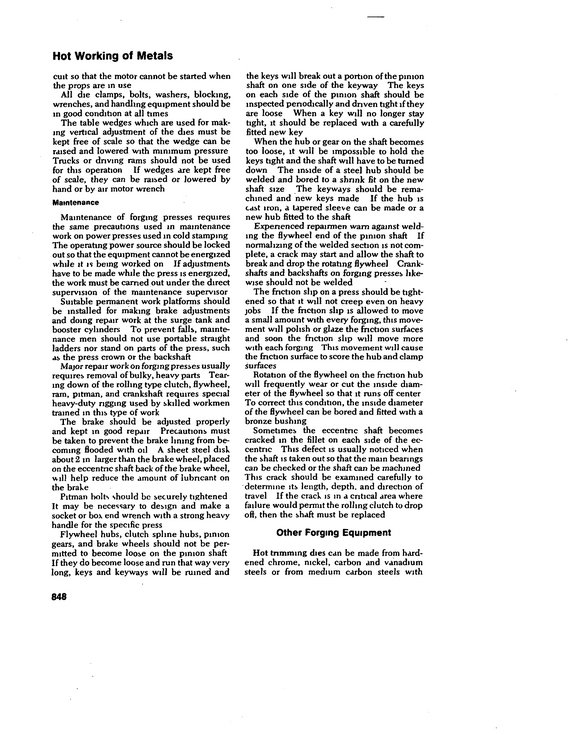
Fig 31-1 --Well-designed manifold system for acetylene cylinders Courtesy Linde Co , Division of Union Carbide Corp Most welding and cutting processes --for construction, demolition, maintenance, and repair--use portable, manually operated equipment The major portion of this chapter discusses ways of minimizing the hazards encountered in this type of intermittent op eration Since production line welding and cutting equipment is usually permanently installed, the source of a hazard can be mini mized through safe design The safety pro fessional, however, can use this chapter to help him check the operation and mainte nance of production line equipment The detailed specifications of ASI Stand ard Z49 1, Safety in Welding and Cutting, should be followed In addition, city, state, and Federal government codes and regula tions, where applicable, should be consulted This chapter uses the American Welding Society's welding and cutting definitions A welder is "one who is capable of per forming a manual or semiautomatic welding operation " A welding operator is "one who operates machine or automatic welding equipment " Gas Welding and Oxygen Cutting An oxygen-cutting process severs or re moves metal by the chemical reaction of the metal with oxygen at an elevated temperature maintained with heat from the combustion of fuel gases In the powder-cutting process, a finely divided material, such as iron powder, is added to the cutting oxygen stream The powder bursts into flame in the oxygen stream and starts cutting without preheating the ma terial to be cut Powder cutting is used on stainless and other steels, on many nonferrous metals, and on concrete in construction and demolition jobs Welding and cutting gases Oxygen is furnished to the consumer in steel cylinders, usually under a pressure of about 2200 psi at 70 F, or as a liquid to be gasified on the consumer's premises Pure oxygen will not bum or explode It supports combustion, that is, it causes other substances to bum when they are raised to the kindling temperature Combustible ma terials bum much more rapidly in oxygen than in air Oxygen forms explosive mixtures in certain proportions with acetylene, hydro gen, and other combustible gases A gas-welding process unites metals by heating them with the flame from the com bustion of a fuel gas or gases and sometimes includes the use of pressure and a filler metal This chapter was revised by Joseph Van Sickle, based upon reviews by selected members of the National Safety Council 919
refid# oRYK0kejejgo6wLVz7vyDpNo1 page
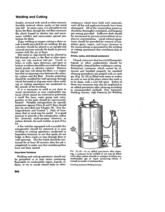
Welding and Cutting ferably, covered with metal or other noncom bustible material where sparks or hot metal may fall In some cases, it is advisable to wet down the floor, though the wet floor increases the shock hazard to electric (arc and resist ance) welders and necessitates special pro tection for them If gas welding or oxygen cutting is done in side a booth provided for arc welding, the gas cylinders should be placed m an upright and secured position outside the booth to prevent contact with the arc or flame Hot metal or slag should not be allowed to fall through cracks in the floor or other open ings, nor into machine tool pits Cracks or holes in walls, open doorways, and open or broken windows should be covered with sheet metal guards or asbestos curtains Because hot slag may roll along the floor, it is impor tant that no openings exist between the asbes tos curtain and the floor Similar protection should be installed for wall openings through which hot metal or slag may enter when weld ing or cutting operations are conducted on the outside of the building If it is necessary to weld or cut close to wood construction or near combustible ma terial which cannot be removed or protected, a small fire hose, water pump tank extin guisher, or fire pails should be conveniently located Portable extinguishers for specific protection against Class B and C fires should also be provided (see Chapter 36, "Fire Ex tinguishment and Control ") Pails of lime stone dust or sand may be useful It is good practice to provide a fire extinguisher, either drv chemical, multi-purpose chemical, or carbon dioxide, for each welder, as part of his kit A fire watcher equipped with a suitable fire extinguisher should be stationed at or near welding or cutting operations conducted in hazardous locations to see that sparks do not lodge m floor cracks or pass through floor or wall openings The fire watch should be con tinued for at least 30 minutes after the job is completed, to make sure that smoldering fires have not been started Hazardous locations Welding and cutting operations should not be permitted m or near rooms containing flammable or combustible vapors, liquids, or dusts, or on or inside closed tanks or other containers which have held such materials, until all fire and explosion hazards have been eliminated All of the surrounding premises should be thoroughly ventilated, and frequent gas testing provided Sufficient draft should be maintained to prevent accumulation of ex plosive concentrations Local exhaust equip ment should be provided for removal of haz ardous gases, vapors, and fumes (piesent in the surroundings or generated by the welding or cutting operations) that ventilation fails to dispel Drums, tanks, and closed containers Closed containers that have held flammable liquids or other combustibles should be thoroughly cleaned before welding or cutting Sometimes containers which cannot be re moved and handled properly for standard cleaning procedures are purged with an inert gas (Fig 31-10) or filled with water to within an inch or two of the place where the work is to be done, with a vent left open Either of these two measures may also be employed as an added precaution after cleaning according to recommended methods (See American Welding Society Safe Practices for Welding VENT FlC 31-10 -- an added precaution after clean ing, a container to be welded or cut may be filled with either carbon dioxide or nitrogen to dilute any combustible gas or vapor remaining--dilute it enough to render it nonhazardous Courtesy American Welding Society 940
refid# 7Op0nvaLwyGa1XXd77pRqbode1 page
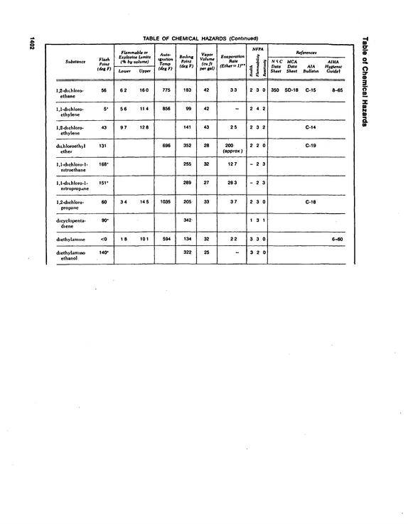
Table of Chemical Hazards 1402 Substance TABLE OF CHEMICAL HAZARDS (Continued) Flammable or Explosive Limits (% by volume) (deg F) Lower Upper Auio* tgmtion Temp (deg F) Boiling Point (deg F) Vapor Votume (cuft per gal) Evaporation Rate (Ether** 1)** NFPA & j i!
refid# R09NKGdyewxRex2dG2p9R0B71 page
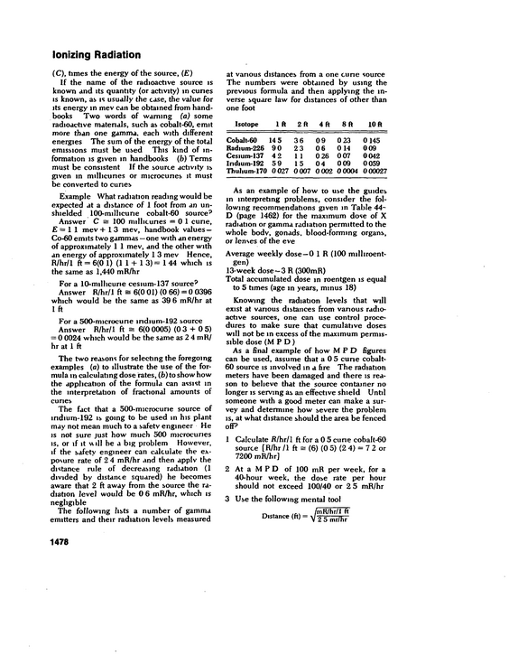
Ionizing Radiation (C), times the energy of the source, () If the name of the radioactive source is known and its quantity (or activity) in cunes is known, as is usually the case, the value for its energy m mev can be obtained from hand books Two words of warning (a) some radioactive materials, such as cobalt-60, emit more than one gamma, each with different energies The sum of the energy of the total emissions must be used This kind of in formation is given in handbooks (b) Terms must be consistent If the source activity is given in millieunes or microcunes it must be converted to curies Example What radiation reading would be expected at a distance of 1 foot from an un shielded 100-milhcune cobalt-60 source'* Answer C s= 100 millieunes =01 cune, E = I 1 mev +13 mev, handbook values -- Co-60 emits two gammas--one with an energy of approximately 1 1 mev, and the other with an energy of approximately 1 3 mev Hence, R/hr/1 ft = 6(0 1) (1 1 + 1 3) = 1 44 which is the same as 1,440 mR/hr For a 10-millicurie cesium-137 source?
refid# 8VR2eL0D5V71EJaO0ox88kZ8m1 page
Motorized Equipment Vehicles should be moved in low gear and at low speed inside shop areas, especially up and down ramps Training repair shop personnel Apprentices and new employees should be trained to do each job in the most efficient manner Job instruction should include the safety rules and regulations pertaining to each job and give the reasons for such rules The new mechanic should be thoroughly in doctrinated concerning the company's policy toward safety He should understand the organization of the safety program and the part he is expected to play m it Having been indoctrinated and trained to work safely, the new employee must be kept actively interested m observing accepted safe practices m the conduct of his job There are many devices available to the safety di rector to accomplish this end, including safety supervision, safety contests, safety meetings, posters, safety bulletins, and pamphlets Proper application of these various incen tives is descnbed elsewhere m this Manual This safety director should select those most suitable to his purpose and adapt them as needed Off-the-Road Motorized Equipment Heavy-duty trucks are again mentioned here because they are used extensively for special off-the-road operations m such in dustries as mining and construction When on the road, they are, of course, governed by the same safe-dnving practices as other types of automotive equipment The use of heavy-duty trucks, mobile cranes, tractors, bulldozers, and other mo torized equipment in the production of stone, ore, and similar materials and in construction work is often accompanied by serious ac cidents Workers near equipment can be struck, run over, and killed Equipment sometimes slips over embarkments, injuring people Servicing and maintaining equip ment can be hazardous Many accidents, even those that do not injure anyone, result in cosdy damage to equipment, loss of efficiency and production, and high maintenance costs In general, prevention of accidents to heavy equipment requires 1 Safety features on equipment, 2 Systematic maintenance and repair, 3 Trained operators, and 4 Trained repairmen Safe and proper operation of equipment should be found in manufacturer's manuals Many driving practices are the same as those necessary for the safe operation of highway vehicles Off-the-road driving, however, involves special hazards requinng special training and safety measures Haul-roads Roadway improvements pay for them selves because they reduce accidents and lower maintenance costs Both temporary and permanent roads often are too narrow for the equipment and for two-way traffic, es pecially at curves and fills Enough space must be provided at curves so that large trucks need not cross the centerline of the road Curves should be elevated toward the out side Roadways for heavy-duty trucks and twoway traffic in open pit mines should be 40 to 50 ft wide Sized rock and sand with clay and oil for binders make a satisfactory road Roads ofheavy rock, filled with rock ofsmaller sizes and surfaced with fine rock, also stand up well under heavy traffic Roadways should have a slight crown and ditches for drainage The maximum grade should not exceed 8 per cent A windrow of loose material along the bank side fur nishes protection against the truck's going off the roadway For night driving, reflectonzed signs along the bank side will in crease safety Both temporary and permanent roadways require regular patrolling and maintenance Too often serious accidents, breakdowns, delays, and unnecessary maintenance ex pense can be traced to neglected temporary roadways Road patrols should be provided with protective equipment, such as barri cades, Men Working signs, red flags, flag men, and flares Seasonal conditions create road hazards which require prompt attention Some com panies provide sprinkler trucks to protect their men against harmful dusts, discomfort, and the possibility of accidents during dry 1558
refid# rx2k51v43e7LVRBypOeQ3mRkr1 page
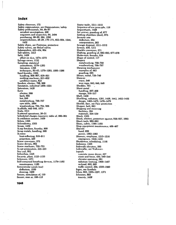
Index Safety observers, 172 Safety organizations, see Organizations, safety Safety professionals, 64, 86-87 accident investigation, 268 engineers and inspectors, 64, 1494 purchasing, 98-99, 384, 1292 responsibilities, 28-29, 170-171, 853-854, 1244, 1432 Safety shoes, see Footwear, protective Safety valves, see Relief valves Salamanders, 433-434, 804 Salt tablets, 1213 Salts, 1428 effect on skin, 1274-1275 Salvage crews, 1132 Sampling, statistical instruments, 1279-1283 literature, 1295 techniques, 62-63, 1279-1283, 1285-1286 Sand foundry, 1255 handling, 806-807, 820-821 molding machines, 821-822 sandblast rooms, 823 Sanders, electric, 798, 969 Sanitation, industrial 1206-1221 Saturation, 1428 Saws electric, 968 hack, 955 hot, 849 metalworking, 756-757 rpm table, 1604 woodworking, 784-794,956 Scaffolds, 442-448, 1573 Scala, 1511 Scattered operations, 30-31 Scheduled charges (injuries), table of, 260-261 Scintillation counter, 1439 Sclera, 1325 Scleroderma, 1325 Scram, 1439 Scrap breakers, foundry, 809 Scrap metals, handling, 508 Screens heat-reflecting, 910-911 projection, 229 Screw conveyors, 572 Screw drivers, 962 Screw machines, 752-753 Script preparation, 222-223 Sea coal, 802 Seborrhea, 1325 Security, plant, 1133-1135 Selenium, 1371 Self-contained breathing devices, 1179-1182 maintenance, 1185 Semicircular canals (ear) definition, 1520 drawing, 1509 Senses, stimulation of, 110 Sensor, man as, 108-113 1648 Septic tanks, 1211-1212 Sequence-of-use principle, 118 Sequestrants, 1428 Set screws, guarding of, 677 Settling chambers (dust), 875 Seventy rate definition, 254 interpretation, 263 Sewage disposal, 1211-1212 Sewers, 459, 1211 Shackle conveyors, 571 Shalting, guarding of, 662-663, 677-678 Shake-outs, foundry, 824 Shape of control, 117 Shapers metalworking, 758-759 woodworking, 796-797 Sheanng mechanisms examples of, 663 guarding, 685 Shears, metal, 739-740 Sheaves crane, 540 wire rope, 643, 646, 648 Shedder, 701 Sheet metal handling, 507-508 storage, 516-517 Shell, 1439 Shielding, radiation, 1291, 1439, 1442, 1452-1455 design, 1463-1473, 1476-1479 Shields, face, see Face protection Shipper, belt, 683 Shipping and receiving facilities, 394 matenals, 524-530 Shock, 1325 Shock, electnc, protection against, 936-937, 1003 Shock tools, 962-963 Shoes, safety, 1190-1193 Shop equipment maintenance, 466-467 Shovels hand, 959 power, 1562-1565 Showers, employee, 1215-1216 emergency, 1232-1233 Shutdowns, scheduling, 1116 Siderosis, 1325 Sidewalk elevators, 595 Sidewalks, see Walkways Signals concrete mixer driver, 427 crane and hoise, 450, 540-544 elevator operating, 591 radiation warning, 1466-1467 railroad, 602, 605 traffic control, 394, 1559-1560 Signs, see Symbols Silica, 803, 1255-1257, 1371 Silicones, 803 toxicity, 1428
refid# o6oE2eyVb36rk0Dd1rJYXnbr1 page
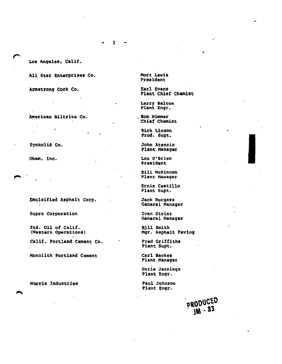
n Lob Angeles, Calif.
refid# 44Ng3wXRoa3V2kOpvOoq9ZyaR1 page
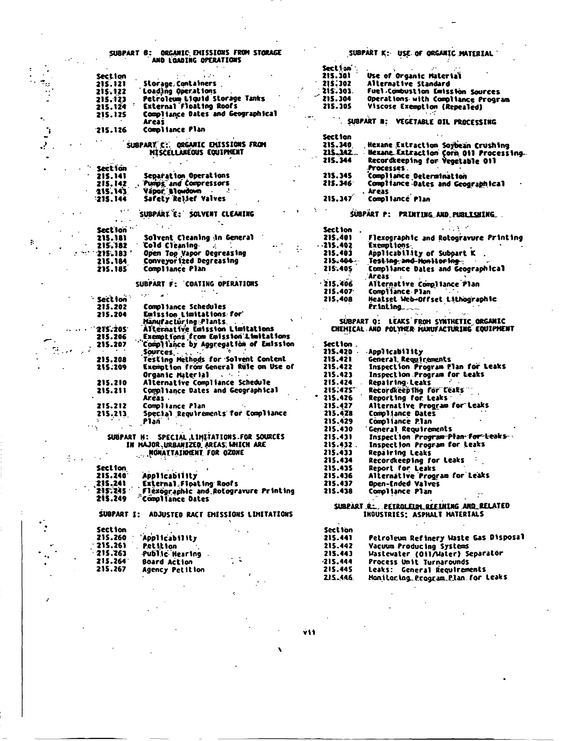
SUBPAST 0: ORGANIC* EMISSIONS FROM STORAGE AMO LOADING OPERATIONS Section 21$.121 Storage,Containers . 21$.122 loading Operations 215.123 Petroleum liquid storage Tanks 21$.124 ' External Floating Roofs 21$. 12$ Coopl 1an<ce Oates and Geographical Areas 215.126 Compliance Plan SUBPARf C:.
refid# DMwy2bQNxE778ZoBJB94XY67n1 page