Refine
Estimated Years UndatedClear
92,592 results foundRefine Search
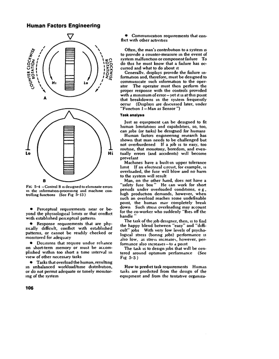
Human Factors Engineering V FlC 5-4 --Control B is designed to eliminate errors m the information-processing and machine con trolling functions (See Fig 5-13 ) Perceptual requirements near or be yond the physiological limits or that conflict with established perceptual patterns Response requirements that are phy sically difficult, conflict with established patterns, or cannot be readily checked or monitored for adequacy Decisions that require undue reliance on short-term memory or must be accom plished within too short a time interval in view of other necessary tasks Tasks that overload the human, resulting m imbalanced workload/time distribution, or do not permit adequate or timely monitor ing of the system Communication requirements that con flict with other activities Often, the man's contribution to a system is to provide a counter-measure in the event of system malfunction or component failure To do this he must know that a failure has oc curred and what to do about it Generally, displays provide the failure in formation and, therefore, must be designed to communicate such information to the oper ator The operator must then perform the proper response with the controls provided with a minimum of error-- yet it is at this point that breakdowns in the system frequently occur (Displays are discussed later, under "Function 1 --Man as Sensor") Task analysis Just as equipment can be designed to fit human limitations and capabilities, so, too, can jobs (or tasks) be designed for humans Human factors engineenng research has shown that man needs to be challenged but not overburdened If a job is to easy, too routine, that monotony, boredom, and even tually errors (and accidents) will become prevelant Machines have a built-in upper tolerance limit If an electncal circuit, for example, is overloaded, the fuse will blow and no harm to the system will result Man, on the other hand, does not have a "safety fuse box " He can work for short penods under overloaded conditions, e g, high production demands, however, when such an overload reaches some undefinable point, the human mav completely break down Such stress overloading may account for the co-worker who suddenly "flies off the handle " The task of the job designer, then, is to find the happy blend between "easy" and "diffi cult" jobs With very low levels of psycho logical stress (boring jobs) performance is also low, as stress increases, however, per formance also increases --to a point The task is to design jobs that will be cen tered around optimum performance (See Fig 5-5) How to predict task requirements Human tasks are predicted from the design of the equipment and from the tentative organiza- 106
refid# 5D7qX2VoBwYEreOBvaRnXgDyN1 page
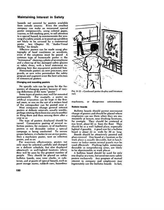
Maintaining Interest in Safety hazards not covered by posters available from outside sources Even the smallest company can make an occasional special poster inexpensively, using colored paper, crayons, or felt marking pens, to call attention to a special hazard, to commemorate the win ning of a safety award, or to point up a problem not likely to be covered by a commercial poster See Chapter 10, "Audio-Visual Media," for details Effective posters can be made using pho tographs of local conditions or accidents, even if the situations must be posed A common type of homemade poster is the "testimonial" showing a photo ofan employee and a close-up of his damaged safety glasses or safety shoes, with a brief statement ex plaining how this equipment protected him Homemade posters on new processes, new guards, or new rules personalize the safety program and augment even the best selection of commercial posters Changing and mounting posters No specific rule can be given for the fre quency of changing posters because of vary ing definitions of the term "poster " Some types of posters may well be mounted permanently For example, a poster on artificial respiration can be kept in the firstaid room, or one on the use of a certain kind of fire extinguisher can be posted near it Most companies change general interest posters at definite intervals, usually weekly, perhaps rotating them from one area to another or filing them and then reusing them after a year or so The type of posters displayed should be varied Consecutive posting of several in fection posters, for instance, or of machinery posters is not desirable unless a special campaign is being conducted To secure proper balance, it is better to use an eye poster, then a machinery poster, next an infection poster, and so on For maximum effectiveness, posters not only must be selected carefully and changed on a definite schedule, but also displayed attractively m well-lighted locations where they will be seen by the greatest number of people They should be placed on safety bulletin boards, near time clocks, m cafe terias, and at points of special hazard, such as paint storage rooms, rubbish cans, hazardous Fig 8-15 --Combined poster display and literature rack machinery, or dangerous intersections Bulletin boards Bulletin boards should permit convenient change of posters and should be placed where employees can see them when they are mo mentarily at leisure, near drinking fountains, for example They should be centered at eye level, about 63 in from the floor They should be in a well lighted place, especially lighted if possible A good size for a bulletin board is about 22 m wide by 30 in long Boards should be attractively painted and glass-covered One board at a location in the work place is usually desirable, but in lunch rooms or locker rooms several panels mav be used effectively Flashing lights sometimes desirable in nonproducing areas, are likely to be objectionable in work places A bulletin board should be used for only one display at a time, but need not carry safety posters exclusively Any program of mutual interest to company and employees may legitimately use the bulletin boards In fact. 190
refid# J3bOqBwzV8n5paONmD58wG5w61 page
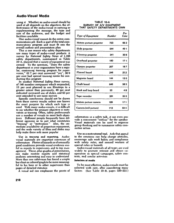
Audio-Visual Media using it Whether an audio-visual should be used at all depends on the objective, the ef fectiveness of the audio-visual m carrying or supplementing the message, the type and size of the audience, and the budget and facilities available One audio-visual cannot do the entire com munications job Each is part of the total com munications program and must fit into the overall outline and presentation plan This is one reason why safety departments use many tvpes of audio-visual products A survey by National Safety News of 1,108 safety departments, summarized in Table 10-A, showed that a variety of equipment was owned To the question, "Does the safety department in your organization have a regu lar, continuing training program for super visors," 61 7 per cent answered "yes", 56 9 pier cent had special training rooms for con ducting this program In another National Safety News survey, of 146 member companies which responded, 13 per cent planned to use filmstrips to a greater extent than previously, 48 per cent indicated increased use of slides, and 63 per cent intended to use more movies Specific conclusions should not be drawn from these survey results unless one knows the exact purpose for which each type is used With many audio-visuals, it is difficult to say whether the primary objective is moti vation or training Often, safety professionals use a number of visuals to meet both objec tives Different people frequently have dif ferent opinions as to just what constitutes "training" or "motivation " Also, the im mediate availability of projection equipment, and the wide variety of films and slides may help make these aids more popular Use in training and reporting.
refid# 3QBJg139j6X2xvxJaBdvRKoMJ1 page
Workmen's Compensation, General Liability, and Disability Insurance fairly accurate estimate must be made of the frequency and the seventy of the losses that may be expected Usually, the state agency admimstenng the coverage requires proof of financial re sponsibility from the nsk and other guarantees in the form of a bond or secunty if a company expects to self-insure Administration States vary widely on methods of admin istration, but workmen's compensation com missions or boards and the courts are commonlv used Administration by special commissions or boards may be more efficient than administration by the courts, primarily because the handling of compensation claims involves highly specialized procedures and needs the attention of specialists Courts often are not able to spend the time necessary to handle the multitude of compensation cases which anse In the handling of compensation claims, there are four methods in general use 1 A written agreement is made between the employee and the employer (or his earner) setting forth the amount ofbenefits, weekly wage, and other pertinent facts This agreement, with the report of accident and medical records, is filed with the board or commission admimstenng the act for its approval 2 The carrier begins payments directly to the injured worker, following the specified waiting penod He files a statement with the board or commission that compensation is being paid and gives the date on which payment was first made The board or commission then checks the accident report and medical records to see if pay ments are properly handled 3 In states having exclusive state funds, the injured worker must formally petition for benefits His statements are examined bv the administrative authority, and if his statements are in order, benefits are paid 4 In contested cases, a hearing or trial is held by the board or commission --the facts are reviewed, witnesses are heard, and the evidence concerning the case is revealed The board or commission then decides whether to grant or to disallow the benefits The burden of proof is usually on the employee Most states provide for an appeal by either party on questions of law, and about half the states allow an appeal on questions of both law and fact Every state requires the employer to report injuries sustained by his employees in the course of their employment The majority of states require only that injuries which cause disability of a stipulated duration, such as for one day, three days, seven days, or fourteen days, be reported Failure to report can bring penalties fines from $25 to $1,000, and in a few instances, imprisonment The workmen's compensation laws usually state that the employer be given notice of an accident by the employee as soon as pos sible, at least within 30 days Notice of the accident must give the approximate date and place of the accident, if known, and m most instances may be given either orally or m writing Failure to comply with this require ment may be excused by the industrial com missioner under certain special conditions Inaccuracy or delay in giving notice is no bar to recovery unless the employer was prejudiced thereby Compensation may be reduced or denied to the extent of the justi fiable prejudice of the employer or for his failure to report the injury within designated limits The time limit for reporting occupational disease is usually longer than that required for injury The day that disability from occu pational disease begins is considered the day of injury for determining when compen sation is to begin The time limits within which compensation may be claimed m the various states range from six months to six years, but one or two years are most frequently specified Some commissions permit tardy claims if justified by the merits of the case Rehabilitation The definition of rehabilitation, as given m a report published by the American College of Surgeons, is "the planned attempt through the use of all recognized measures, under skilled direction, to restore those persons who because of disabilities do not assume to the 300
refid# MMRBzEzQ3oqr89kyK9xVxO70a1 page
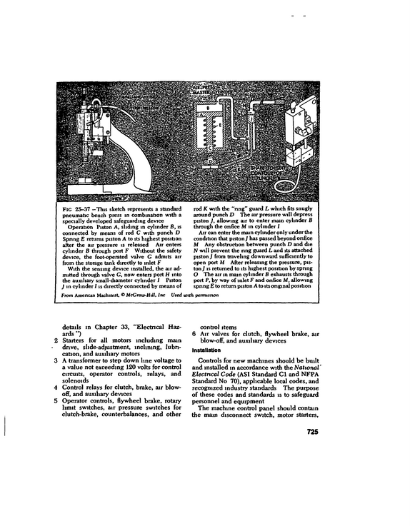
FlC 25-37 --This sketch represents a standard pneumatic bench press in combination with a specially developed safeguarding device Operation Piston A, sliding in cylinder B, is connected by means of rod C with punch D Spring E returns piston A to its highest position after the air pressure is released Air enters cylinder B through port F Without the safety device, the foot-operated valve C admits air from the storage tank directly to inlet F With the sensing device installed, the air ad mitted through valve C, now enters port H into the auxiliary small-diameter cylinder / Piston J in cylinder I is directly connected by means of rod K with the "nng" guard L which fits snugly around punch D The air pressure will depress piston J, allowing air to enter main cylinder B through the onfice M in cylinder I Air can enter the main cylinder only under the condition that piston J has passed beyond onfice M Any obstruction between punch D and die N will prevent the nng guard L and its attached piston ] from traveling downward sufficiently to open port M After releasing the pressure, pis ton J is returned to its highest position by spnng O The air in main cylinder B exhausts through port P, by way of inlet F and onfice M, allowing spnng E to return piston A to its ongmal position From American Machinist, McCraw-Htll, Inc Used with permission details in Chapter 33, "Electrical Haz ards ") 2 Starters for all motors including main drive, slide-adjustment, inclining, lubri cation, and auxiliary motors 3 A transformer to step down line voltage to a value not exceeding 120 volts for control circuits, operator controls, relays, and solenoids 4 Control relays for clutch, brake, air blowoff, and auxiliary devices 5 Operator controls, flywheel brake, rotary limit switches, air pressure switches for clutch-brake, counterbalances, and other control items 6 Air valves for clutch, flywheel brake, air blow-off, and auxiliary devices Installation Controls for new machines should be built and installed m accordance with the National' Electrical Code (ASI Standard Cl and NFPA Standard No 70), applicable local codes, and recognized industry standards The puipose of these codes and standards is to safeguard personnel and equipment The machine control panel should contain the main disconnect switch, motor starters. 725
refid# Kzzo8nbgY2yoV55DmkyEMk86w1 page
Cold Forming of Metals by an authorized person who should observe his methods for a few minutes to see that he is operating the press correcdy Removing dies Dies should be removed from the press with the same care used in setting them up Although modifications may be necessary in special cases, the safe procedure is as fol lows 1 Make sure that the working space is cleared of all stock, containers, tools, and other items 2 Disconnect or shut off the power and lock the switch Tum the flywheel by hand or by means of the bar until the slide is at the bottom of the stroke If the press cannot be turned over manually, jog it under power, then shut off the power and lock the switch 3 Dismantle or disconnect the pomt-ofoperahon safety device only if absolutely necessary Put aside the parts of a dis mantled safety device so that it can be reinstalled in good condition as soon as the new die is in place 4 Clean off the bolster plate, preferably with a brush 5 If the die is to be operated with an air pad, shut off the air supply and open the release valve to permit the pins to go down Also shut off the air supply to the automabc blowout system used in the die 6 Loosen and remove bolts and clamps bolting the die to the slide and to the bolster plate Place bolts, nuts, and clamps on a bench or in a special place on the die truck as soon as they have been removed from the press 7 Make certain that the die is loose and that bolts, nuts, clamps, and other obstructions have been removed 8 Raise the slide slowly, manually on light presses, and by jogging or inching under power on large presses, and make sure that the die does not hang in the slide 9 Block the slide in its highest position, and if power was used, shut off the power and lock the switch 10 Place the die truck close to the press, adjust the table to the same height as the bolster plate, and chock the wheels or set the brake of the truck to prevent move ment To pull the die onto the truck, use a hook engaged so that it cannot slip 11 Dies should be inspected, repaired, and protected before being stored for the next run Inspection should include pins, bushings, etc Hardened dies and punches should be stored in closed posi tion with a piece of soft wood between the cutting edges to protect them In juries have occurred when hardened dies were handled when open or partially open, as a sudden jolt can cause them to close and pinch a hand or finger Inspection and Maintenance Twenty per cent of the senous-injury acci dents associated with presses are traceable to malfunction of press, guards, or other safety devices The best press safety program m the world cannot succeed, nor can top production be met without good inspection and main tenance of both press and guarding devices Inspection, adjustment, and repair ofpower presses and related equipment can only be done by competent, thoroughly trained men These men must be fully familiar with the construction and operation of the equipment they are responsible for They also must be equipped with the tools and equipment, properly sized, to assure good workmanship with safety for all The area around the press being worked upon should be cleared of all personnel not directly involved in the maintenance Flash ing warning lights or other barriers or bar ricades should be set out to mark the tempo rary area of maintenance to all crane operators and other matenal and equipment handlers Stationing an idle crane, on guard, is an acceptable alternative When inspection or work to be performed involves any electrical item, or when ac cidental starting of the equipment would create a hazard, the main disconnect switch must be opened to deenergize the power source Lock out the main disconnect and place a Danger--Hold Off tag on the con trol panel 734
refid# Z8jVaRj947GX64oqKnEwdVY7Z1 page
should be applied to the press brake In addi tion to the electro/pneumatic dutch and brake controls, there should be gate or barrier guard ing at the point of operation (Fig 25-52) Stroke control A limited range of strokes is available in standard press brakes Small press brakes may have as little as a one and one-half-inch stroke, large press brakes as much as a sixinch stroke The ram is adjustable to suit the closed height of the dies On press brakes this is accomplished by changing the length of the connections through the use of adjust ment screws Treadle controls To provide the greatest versatility for the large variety of work per formed on a general purpose press brake, the basic press brake is equipped with a treadle or pedal Linkage from the pedal connects to the friction clutch and brake of the machine The stopping and holding brake is compres sion spring set, and the clutch is held released The normal state of the press brake, there fore, is stopped or at rest This places the operator in complete control of the press brake Depressing the treadle engages the clutch and releases the brake to activate or cycle the ram By varying the pressure and holding time on the treadle, the operator can control the operation of the press brake for many different operations The ram can be moved incrementally, at varying rates of descent, or continuously as desired This permits an op erator to "slip" the ram to a partially closed position for some types of gauging It also permits him to reposition his hands at the free end of a sheet that must be held or supported, because the sheet will arc upward when the bending work is performed Using the ma chine in this manner is quite common, par ticularly where standard dies are used A foot-operated machine should always be run by a single operator It should not be op erated when other personnel are within reach of the machine working area without the point of operation being guarded Electro/pneumatic clutch and brake con trols In single stroke operations, all controls should be "two hand" palm switches, which must be held down until the dies are closed The palm switches should be spaced so that the operator is required to use both hands When the work requires more than one oper ator, each operator must have his own station with the switches set so that the press brake cannot be cycled until all switches in the cir cuit are depressed When a press brake is equipped with multiple stations, the number of stations "locked m" the circuit may have to be changed for different jobs The "locking m or out" of stations should be ngidly key controlled by supervisory personnel, for there should never be more operators than stations Whenever foot switches are used, provide point of operation protection for the operator The foot switch must be guarded to prevent actuation from falling objects and should not be left unattended by the operator The switch should be turned off, unplugged, and stored when not in use Inching control, when provided, per mits the operator to jog the machine through the cycle and is used only for die setting This form of operation is available through a selec tor switch m the control panel Continuous operation control, if provided, is only to be used with automatic feeds, and with barrier guarding of all pinch points, including the point of operation Speed control Variable speed drive per mits selection ofa speed suitable to the opera tion being performed It is often used to eliminate back bending due to the inertia of wide, thin sheets that extend far to the front of the machine Operating a machine at a re duced speed also facilitates handling of the sheet by the operator Maintenance procedures Preventive maintenance or electncal and mechanical control components must be per formed on a scheduled basis by qualified and trained personnel All press brake compo nents should be given periodic and thorough inspection also to uncover any impending failure or malfunction Any evidence of an unsatisfactory operating condition should be promptly reported and immediately repaired or replaced Tooling should be thoroughly inspected before use and should also receive periodic supervisory inspecbon, in order to maintain i 745
refid# x5aN6Dga803MJn6NKGmbMoZMy1 page
tools frequently and remove from service those found to be defective Many companies have each supervisor check all tools each week A checklist for hand tools considered most hazardous can be helpful in systematiz ing inspection Some workmen prefer to use their own tools even though tools are furnished by the company In this case, supervisors should examine the tools frequently to prevent the use of those that are unsafe If privately owned tools are found to be defective, super visors should insist that they be replaced or that company-owned tools be used instead Carrying tools The workman should never carry tools which in any way might interfere with his using both hands freely on a ladder or while he is climbing on a structure A strong bag, bucket, or similar container should be used to hoist tools from the ground to the job Tools should be returned in the same manner, not brought down by hand, earned m pockets, or dropped to the ground Mislaid and loose tools cause a substantial portion of the hand tool injuries Tools are laid down on scaffolds, on overhead piping, on top of step ladders, and in other locations from which they can fall on persons below Leaving tools overhead is especially hazard ous where there is vibration or where men are moving about Chisels, screw drivers, and pointed tools should never be carried edge or point up in a workman's pocket They should be car ried in a tool box or cart, in a carrying belt like that used by electricians and steel workers, in a pocket tool pouch, or in the hand with points and cutting edges away from the body Tools should be handed from one workman to another, never thrown Edged or pointed tools should be passed, preferably in their carrying case, with the handle toward the receiver Workmen carrying tools on their shoulders should pay close attention to clearances when turning around and should handle the tools so that they will not strike other workmen Maintenance and Repair The tool room attendant or tool inspector should be qualified by training and experi ence to pass judgment on the condition oftools for further use No dull or damaged tool should be returned to stock Enough tools of each kind should be on hand so that when a defective or worn tool is removed from ser vice, it can be replaced immediately with a safe tool Efficient tool control requires periodic in spections of all tool operations These in spections should cover housekeeping m the tool supply room, tool maintenance, service, number of tools in the inventory, handling routine, and conditions of tools Responsibility for such periodic inspec tions is usually placed with the department head and should not be delegated by him When metal tools break in use, there are usually detectable causes overheating or underheating of the forging or steel when it was being hardened, cracks from improper forging, improper tempering, failure to re lieve stresst s in forging, improper quenching, incorrect angle of cutting edge, or steel of poor quality Defects such as these will usually be found m tools of inferior construction, which, because of breakage and inefficiency, are more expensive m the long run than are tools of good quality Therefore, it pays to pur chase tools of the best quality obtainable Hand tools receiving the heaviest wear, such as chisels, wrenches, sledges, star-drills, blacksmith's tools, and cold cutters, require frequent maintenance on a regular schedule Proper maintenance and repair of tools require adequate facilities, workbenches, vises, a forge or furnace for hardening and tempenng, tempering baths, safety goggles, repair tools, gnnders, and good lighting Workmen especially trained in the care of tools should be in charge of these facilities, otherwise tools should be sent out for re pairs Tempenng tools Hammer-struck and striking tools (chisels, stamps, punches, cutters, hammers, sledges, and rock drills) should be made of carefully selected steel and heat-treated so that they are hard enough to withstand blows without mushrooming excessively (Fig 32--4), and yet not be so hard that they chip or crack For safety, it is better that shock tools, 951
refid# N2ZK1a2qYpGmb9verdpDO4n7y1 page
EMERGENCY EXIT INSTRUCTIONS MACHINE SHOP-DAY SHIFT Read Carefully The following persons will be in command in any emergency, and their instructions must be followed CHIEF OF EXIT DRILL-H C Gordon, General Sup't MACHINE SHOP EXIT DRILL CAPTAIN-R L Jones, Foreman MACHINE SHOP MONITORS-Dave Thomas and A L Smith In event of FIRE in machine shop NOTIFY THE GENERAL SUPERINTENDENT'S OFFICE v* PUT OUT THE FIRE, IF POSSIBLE--If the fire cannot quickly be controlled, follow in structions given by Exit Drill Captain R L Jones or by the shop monitors Leave by the exit door at the south end of the shop, if it is blocked by fire, use the door through the toolroom to the outside stairway In event of FIRE or EMERGENCY in other sections of building The general alarm gong will ring for two 10-second periods as an "alert" signal Con tinue work, but be on the alert for the "evacuation" signal, which will be a series of three short rings At the evacuation signal V SHUT OFF ALL POWER TO MACHINES AND FANS TURN OFF GAS UNDER HEAT TREATING OVENS V CLOSE WINDOWS AND CLEAR THE AISLES FORM A DOUBLE LINE IN THE CENTER AISLE AND FOLLOW MONITORS AND EXIT DRILL CAPTAIN TO EXIT--Walk rapidly, but do not run or crowd, do not talk, push, or cause confusion* After leaving the building, do not interfere with the work of the plant fire brigade or the city fire department Await instructions from the General Superintendent or your fore man Returning to the building Return-to-work instructions will be given over the loudspeaker system or by telephone from the Superintendent's office FlC 37-3 --Sample individual instruction notice for general posting 1121
refid# Lg5LGD9p55vRYepvRyBGR5OYQ1 page
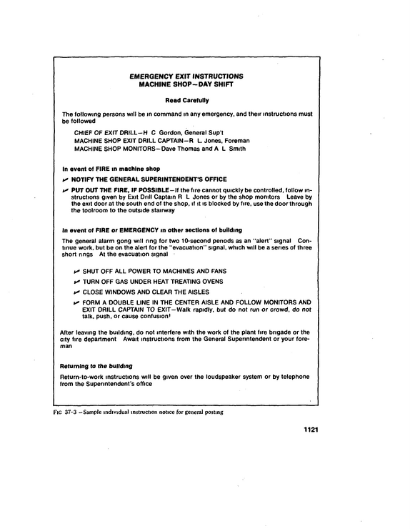
Equipment Selection and Use Select proper tvpe Use equipment properlv Head Protection Safetv hats Bump caps Women s caps Maintenance Ear Protection Insert type Muff type Amount of protection Face and Eye Protection Background and supervision Impact protection Plastic os glass lenses Comfort and fit Face protection Acid hoods and chemical goggles Laser beam protection Other tvpes of protection Respiratory Equipment Respirator selection 1 Air Purifying Respirators Gas masks Chemical cartridge respirators respirators Combination respirators Particulate filter 2.
refid# OJ34GEYqr7MDpVM1g7jBxLQ8j1 page
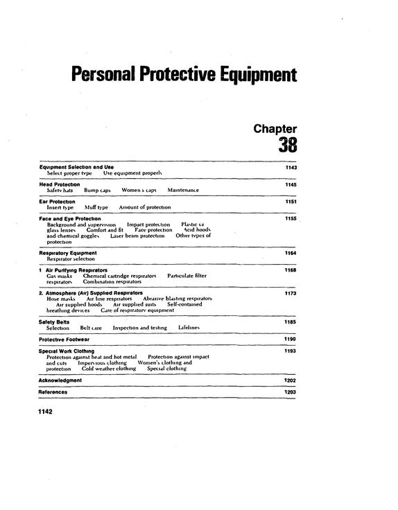
Industrial Hygiene To cooperate in the development of ade quate, effective measures to prevent exposure to harmful agents To examine periodically those employees who are working with or exposed to hazardous matenals To restrict employees from furthur ex posure on a medical basis whenever war ranted by findings of such periodic examina tions Industrial hygiene organization The industrial hygiene organization is primarily responsible for monitoring the work environment and assisting the process engi neer in ensuring that a safe environment is provided and maintained It has a responsi bility To advise appropriate organizations of the potential hazard arising out of any current or proposed process or operation To establish hygienic standards and to make appropnate tests periodically to ensure that the standards are met To specify the design and quality of all types of personal protective equipment and to prescribe standards for their use To recommend controls necessary to minimize employee exposure to harmful environmental factors or stresses To assist the supervisor m educating employees on practices, precautions, and pro cedures established to control their occupa tional exposure To review present and proposed practices and to ensure that they are in accordance with established standards To survey all new installations before they are turned over to shop personnel Safety organization The safety organization plays an integral part in the overall environmental health pro gram Its responsibilities are To conduct an effective safety program by coordinating the educational, engineering, supervisory, and enforcement activities re lated to the safety program To provide educational material for any safety training program for personnel work ing with hazardous matenals To assist the supervisor m teaching his employees safety rules, regulations, and pro cedures To conduct safety surveys to insure that proper practices and procedures are being followed To recommend changes in safety rules, regulations, and procedures to keep pace with technological advancements Purchasing organization The purchasing organization's responsi bilities are to ensure that only equipment and matenals approved by the industnal hygiene, safety, medical, and other appropriate de partments are purchased for use m the com pany Supervisor's responsibilities Each supervisor is responsible for main taining safe working conditions within his organization and for directly implementing the safety program His responsibilities are To maintain a work environment that assures the maximum safety for his employees To make certain that applicants (newly hired or transferred) have been examined by the medical organization and approved for the job before being assigned to work To instruct employees periodically on pre cautions, procedures, and practices to be followed to eliminate accidental exposure to harmful agents To ensure that meticulous housekeeping practices are developed and employed at all times To ensure that food, cands, beverages, other edibles, and tobacco are not stored or consumed in work areas, where toxic ma terials may be present To inform promptly the engineering, industnal hygiene, and safety organizations of any operation or condition which appears to present a hazard to his employees To inform the medical organization 1292
refid# gD663REL7wkLJzb4LRZvzO3ze1 page
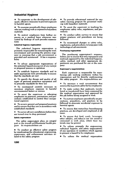
1319 (2 1) C, C, TT =1 T By the Law of Partial Pressures, (3) C, = op, And by Raoult's Law, (4) p, = F,Pf Combine (3) and (4) to obtain (5) C, = aF,p,.
refid# wD8L6mBM5KQjRmEoxnG4ZyQyJ1 page
power sprayers it is advisable to use an ap proved respirator if considerable spray kicks back into tbe operator's breathing zone See Industrial Data Sheet 303 and Hygiemc Guide Decaborane--see Boron hydndes Dems is a powdered plant root, which con tains rotenone as its main active ingredient See Rotenone.
refid# O104gB0vLQgxY6raMNJVLq2dL1 page
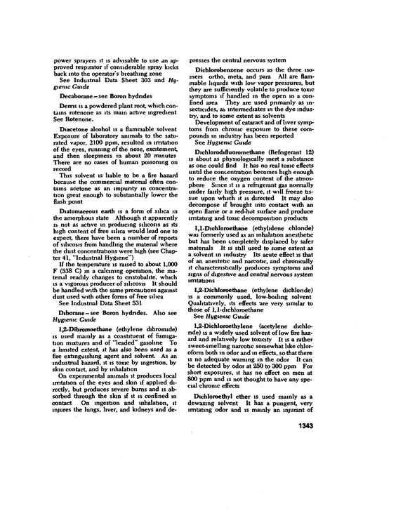
Table of Chemical Hazards 1418 Sub,t,,nce TABLE OF CHEMICAL HAZARDS (Continued) (deg F) Flammable or Explosive Limits (% by volume) Lower Upper Autoignition Temp (deg F) Boiling Point (deg F) Vapor Volume (cuft per gal) Evaporation Rate (Ether** !)
refid# G5yQgO9LQkGwrVG0JZ9YBaX8V1 page
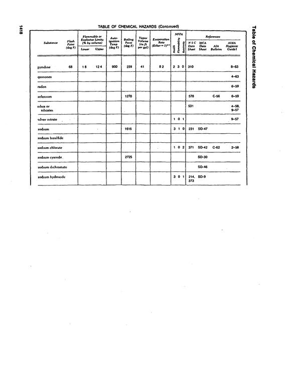
130 120 110 100 90 80 70 60 20 75 150 300 600 1200 2400 4800 75 150 300 600 >200 2400 4800 FlC 45-3 --Three representative octave band analyses the exact frequency of a musician's "concert A" pitch The quality of a sound is deter mined by the number of overtones present and their respective intensities Various musical instruments have different sound spectra Measurement Overall sound levels of steady noises may be measured with a sound level meter (often designated "SLM") The "C" or flat response scale of a sound level meter measures average overall sound pressure level in decibels relative to 0 0002 dyne per square centimeter The meter indicator responds to irregular fluctuations present m steady noise and usually does not remain fixed in one position while a measurement is being made Be cause of these fluctuations, the average of several readings taken at a measuring point is recorded as the overall sound pressure level of the noise at that location The A-scale of a standard SLM is gaining general acceptance for measurement of steady noise to determine the need for hearing con servation programs A-scale measurements indicate the integrated levels of the octave bands from approximately 600 Hz to 10,000 Hz For hearing conservation purposes it is not necessary to obtain detailed octave band analyses An octave-band analyzer (often designated "OBA") consists of a senes of electronic filters that select for measurement each of several octave bands in the noise Most standard analyzers are designed to filter eight octave bands 37 5-75, 75-150, 150300, 300-600, 600-1200, 1200-2400, 24004800, and 4800-9600 (See Fig 45-3 ) The octave bands shown m Table 45-A are recommended as preferred by the Amencan Standards Institute and the International Organization for Standardization Some analyzers are designed to measure sound pressure level in one-third octave bands or in narrow bands of constant width, for example, 5 Hz or 20 Hz Such measure ments are entirely acceptable, but are not necessary for hearing conservation purposes The sound level meter and octave-band analyzer do not measure impulsive noise levels accurately If a noise-exposure m- 1515
refid# 3Jo7My79zyQZeVqxQ6xYZ28kn1 page