Refine
Estimated Years 2000-2009Clear
18,679 results foundRefine Search
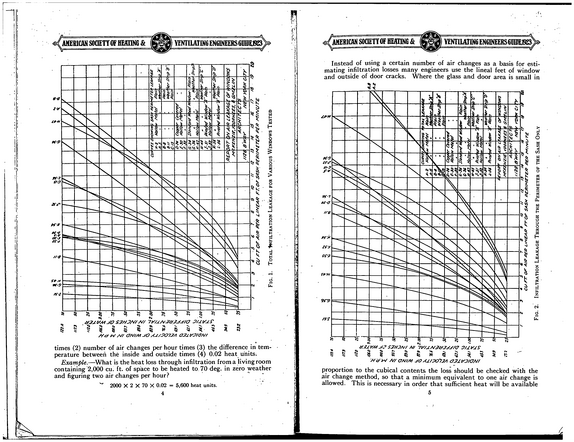
AMERICAN SOCIETYOF BEATING & IYENTI1ATIN6 ENGINEERS GUIDEJ923 ; AMERICAN SOCIETYOF BEATING & YENTIEATIN6 ENGINEERSGDIDE.19230 Instead of using a certain number of air changes as a basis for esti mating infiltration losses many engineers use the lineal feet of window and outside of door cracks.
refid# k99v1NNXOO44owqrN0LaK6g0V1 page
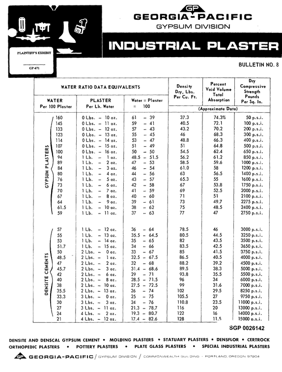
I GYPSUM DIVISION INDUSTRIAL PLASTER GP-671 WATER RATIO DATA EQUIVALENTS WATER Per 100 Plaster j 160 / 145 133 123 114 l/> 107 Q 111 1 100 h 1 94 < 1 89 a. / 84 2E \ =i/*>) a. 1>- o I I 80 76 73 70 67 64 , 61.5 \ 59 PLASTER Per Lb.
refid# pmrYy3Rk11nKrDEXr1pgGnR0j1 page
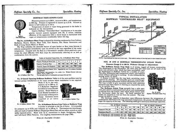
Hoffman Specialty Co., Inc.
refid# kpoLJRkoaRQqbY5Owx0L6nBy1 page
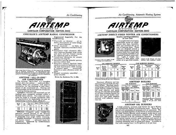
Air Conditioning /7/PTEMP D/V/S/ON Of CHRYSLER CORPORATION DAYTON, OHIO CHRYSLER'S AIRTEMP RADIAL COMPRESSOR Engineered Especially For Air Conditioning.
refid# o9mYQO2e5M9NgJbQvX7EyYJ1w1 page
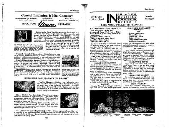
ff Insulation Insulation General Insulating & Mfg.
refid# J0qyv41Ov36qdDv2m4EVGQpO1 page
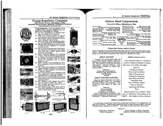
Air System Equipment Air Flow Regulator Young Regulator Company 5209 Euclid Avenue, Cleveland 3, Ohio DAMPER REGULATORS; REMOTE CONTROLS SYSTEMS Sales Representatives in Principal Cities No.
refid# 15zZVn74BgN4wRk8OygnYY9eZ1 page
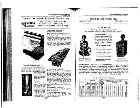
Heating Systems General Automatic Products Corporation (Formerly: General OH Burner Corp.)
refid# nYeZR7Y9K34zZQYoayEVoN0w1 page
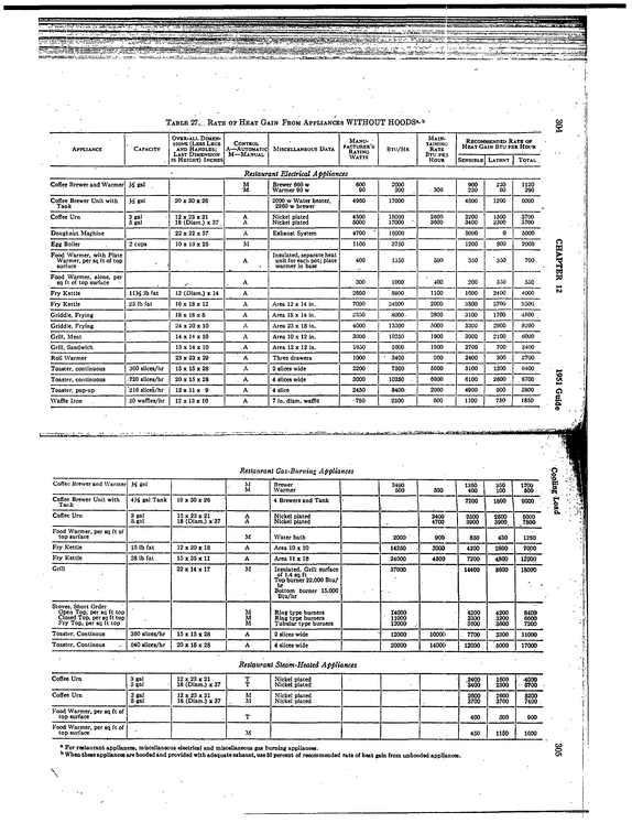
Table 27...
refid# OE081vk54rjnqNr23jka4ZEmw1 page
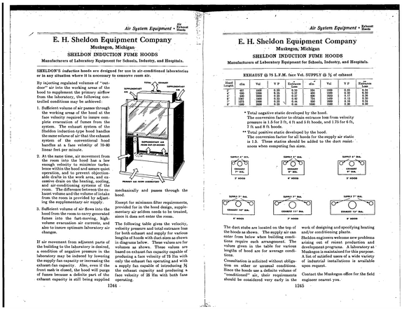
Air Air System Equipment Hwds5* E.
refid# rzkgxJzogNNVME0Z60Nyo1EJ1 page
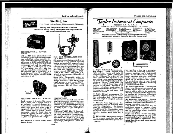
Controls and Instruments Sterling, Inc. 3738 North Holton Street,.Milwaukee 12, Wisconsin Heating and Temperature Control Products Distributed through leading Heating and Plumbing Wholesalers Sales RepresentatiTes in Principal Cities Controls and Instruments 6lcudcr InAirwmwi Com/m/MA / Rochester 1, N.
refid# jmO0Z21oJR619xLOgQnyKZaaQ1 page
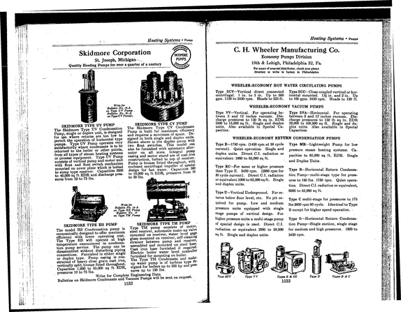
Heating Systems Pumps Skidmore Corporation St.
refid# 6Rb9XBJXVZwvDLvXY5rLeOZro1 page
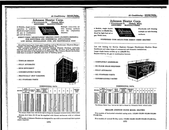
Air Conditioning Industrial Heating Direct Fired Heaters Johnson Heater Corp. 1 Winnisimmet St.
refid# rB4DbwL2bODbXXqpdR56DnMOJ1 page
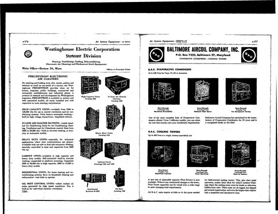
176 Air System Equipment Air Westinghouse Electric Corporation Slurlevanl Division Heating, Ventilating, Cooling, Dehumidifying, Electronic Air Cleaning and Mechanical Draft Equipment Main Office--Boston 36, Mass.
refid# jygbjrGwokZRaG068RMZeDyJZ1 page
Further, affiant sayeth not.
refid# zbM9JYREmpKyNarE8vjq2VqZR1 page
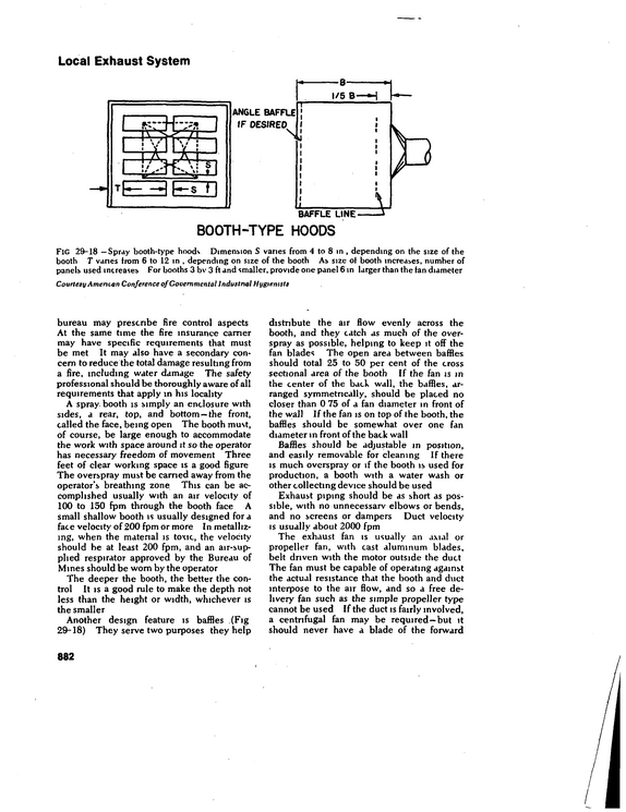
Local Exhaust System BOOTH-TYPE HOODS FlG 29-18 --Spray booth-type hoods Dimension S vanes from 4 to 8 in , depending on the size of the booth T vanes from 6 to 12 in , depending on size of the booth As size of booth increases, number of panels used increases For booths 3 bv 3 ft and smaller, provide one panel 6 in larger than the fan diameter Courtesy American Conference ofGovernmental Industrial Hygienists bureau may prescribe fire control aspects At the same time the fire insurance earner may have specific requirements that must be met It may also have a secondary con cern to reduce the total damage resulting from a fire, including water damage The safety professional should be thoroughly aware of all requirements that apply in his locality A spray booth is simply an enclosure with sides, a rear, top, and bottom --the front, called the face, being open The booth must, of course, be large enough to accommodate the work with space around it so the operator has necessary freedom of movement Three feet of clear working space is a good figure The overspray must be earned away from the operator's breathing zone This can be ac complished usually with an air velocity of 100 to 150 fpm through the booth face A small shallow booth is usually designed for a face velocity of 200 fpm or more In metalliz ing, when the material is toxic, the velocity should be at least 200 fpm, and an air-supplied respirator approved by the Bureau of Mines should be worn by the operator The deeper the booth, the better the con trol It is a good rule to make the depth not less than the height or width, whichever is the smaller Another design feature is baffles (Fig 29-18) They serve two purposes they help distribute the air flow evenly across the booth, and they catch as much of the over spray as possible, helping to keep it off the fan blades The open area between baffles should total 25 to 50 per cent of the cross sectional area of the booth If the fan is m the center of the back wall, the baffles, ar ranged symmetrically, should be placed no closer than 0 75 of a fan diameter in front of the wall If the fan is on top of the booth, the baffles should be somewhat over one fan diameter in front of the back wall Baffles should be adjustable m position, and easily removable for cleaning If there is much overspray or if the booth is used for production, a booth with a water wash or other collecting device should be used Exhaust piping should be as short as pos sible, with no unnecessary elbows or bends, and no screens or dampers Duct velocity is usually about 2000 fpm The exhaust fan is usually an axial or propeller fan, with cast aluminum blades, belt driven with the motor outside the duct The fan must be capable of operating against the actual resistance that the booth and duct interpose to the air flow, and so a free de livery fan such as the simple propeller type cannot be used If the duct is fairly involved, a centrifugal fan may be required--but it should never have a blade of the forward 882
refid# 3LbbwRZNBXeByYQ60qg469vx1 page