Refine
Estimated Years 1940-1949Clear
11,527 results foundRefine Search
3!
refid# daNOdBvzEJ7d1LO0Ve2Z9ejJ51 page
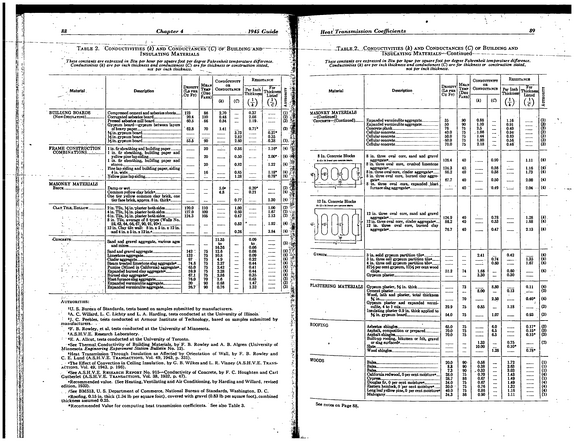
Table 2.
refid# DdGoM1RvJNkgGvemmDQveqrxn1 page
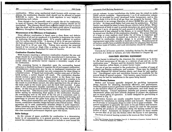
204_____________ Chapter 10_______________________________ 1945 Guide combustion--When using. mechanical draftburners-with average -eon--- .ditions, the combustion chamber draft should not be allowed to exceed 0.02-0.05 in. water.
refid# 4JQem5p7jbmmX5YzKmeMdZpEa1 page
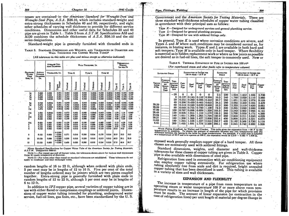
308 .
refid# 1QqMbxRj8jO0r2jY71yMa7p6a1 page
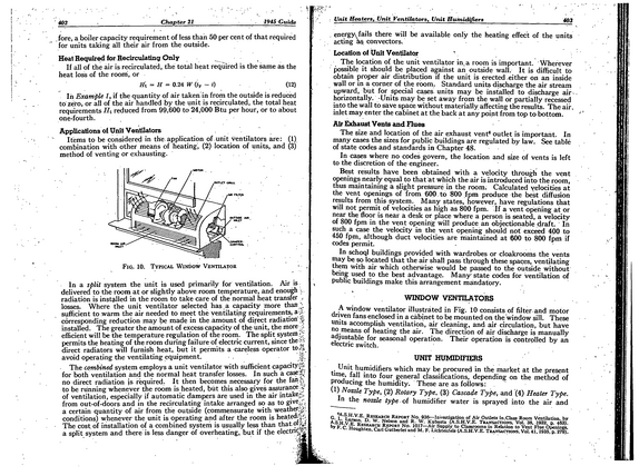
402 Chapter 21 1945 Guide fore, a boiler capacity requirement of less than 50 per cent of that required for units taking all their air from the outside.
refid# BR4mzoNojvbxqbwqXO0q2En4j1 page
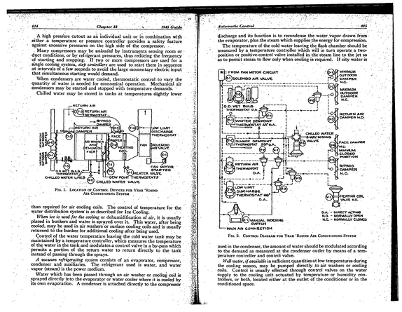
614 Chapter 33 .\ 1945 Guide A high pressure cutout as an individual unit or in combination with .either a temperature or pressure controller provides a safety feature against excessive pressures on the high side of the compressor. .
refid# mgBE90pYm8ZqZwGE84KgVzEQ1 page
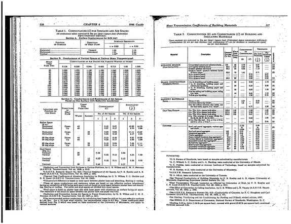
116 CHAPTER 6 1946 Guide Table l.
refid# 2jO2j15Yyn40mvoYmdq2G3ZwR1 page
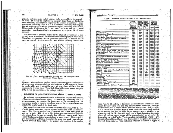
236 CHAPTER 12 1946 Guide provides sufficient relief in hot weather to be acceptable to the majority of users, ft should 'be emphasized, however, that these are borderline cases that may be acceptable largely in the interest of economy.
refid# oerobkLVgpeZZDObJMgRnz46r1 page
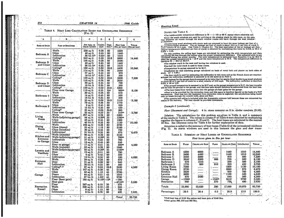
272.
refid# ppQRwwod6nmL10RroVOKjMz4X1 page
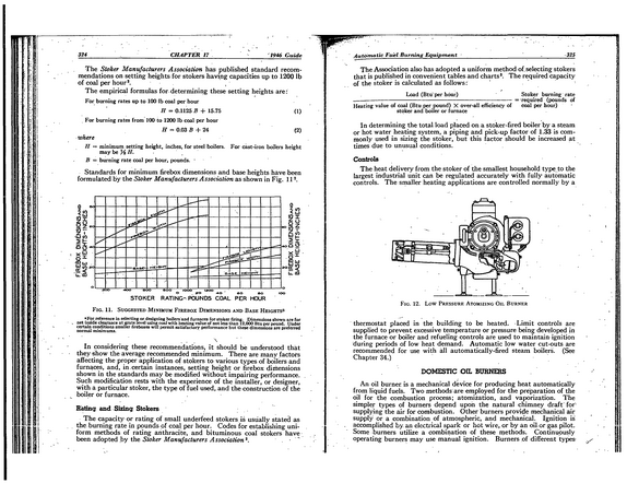
324 , ___________ CHAPTER 17 __________ 1946 Guide The Stoker Manufacturers Association has published standard recom mendations on setting heights for stokers having capacities up to 1200 lb of coal per hour*.
refid# DvXXbmVXgqb691K4V2YYJB0aN1 page
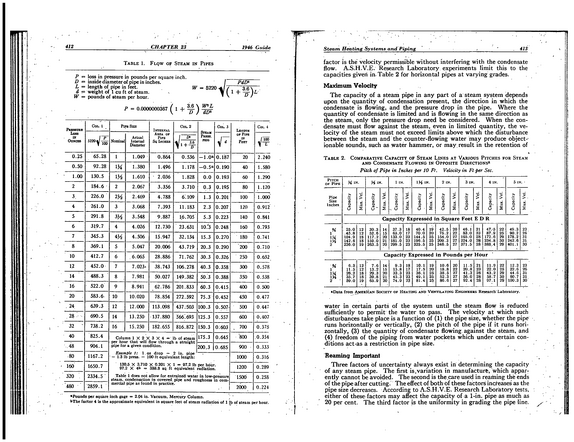
412 CHAPTER 23 1946 Guide Table 1.
refid# by9Qo1b2w77D49pqw0bJeXZLk1 page
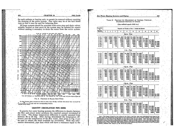
. *54 CHAPTER 24 1946 Guide - (or each radiator or heating unit, to permit its removal without requiring the draining of the entire system. .One valve may be of the lo.ck shield type so that it may be used for balancing flow.
refid# yrY63vL39MrennJnJy55yYQg21 page
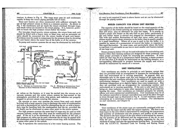
436 CHAPTER 26 1946 Guide receiver, is shown in Fig. 6.
refid# aBqqzxMaO8G6dbB0rydXM5BDY1 page
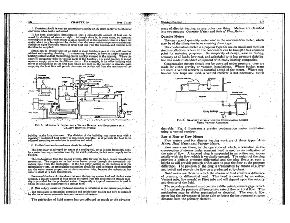
534 CHAPTER 29 1946 Guide . 1.
refid# gDY1B413gyL7Qyk0gRgjwRNQ1 page
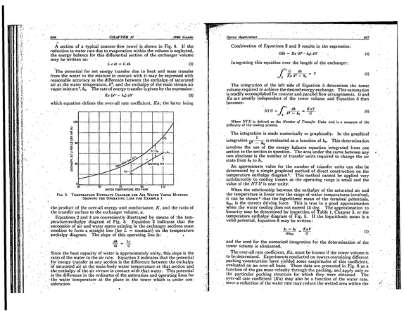
656 CHAPTER 37 1946 Guide A section of a typical counter-flow tower is shown in Fig. 4.
refid# ejJqD0ERRJYpGrNdayG34LQG1 page