Refine
Estimated Years 1930-1939Clear
8,921 results foundRefine Search
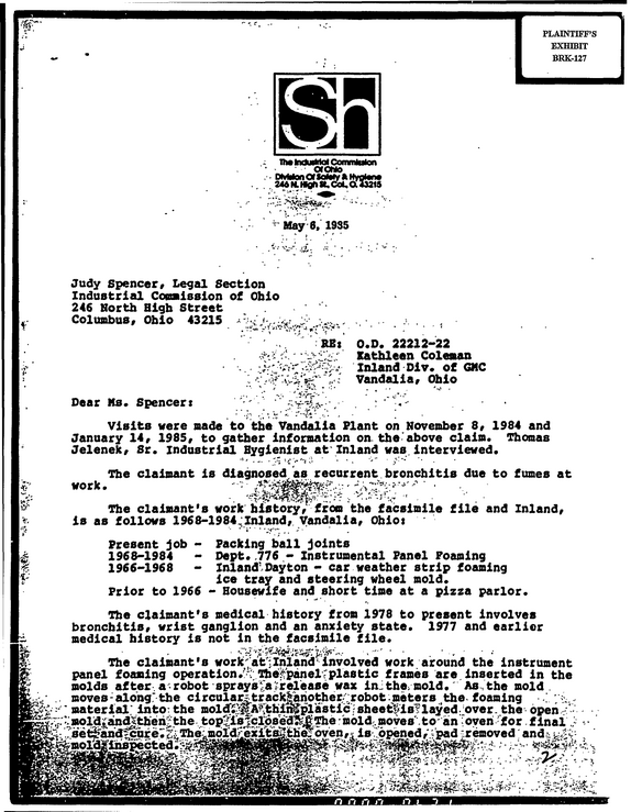
ir TTw MwMal Commtolon CWONO HMtw^nonfiv/yiMffMjjiiivi i4iifya--if--n----v-- .2-4--5--1--1--W- fatfSt St, CMot,0143215 5 May 6, 1935 * Vj :t .
refid# gbRz1OrDxyj0DjZady1OqZY9a4 pages
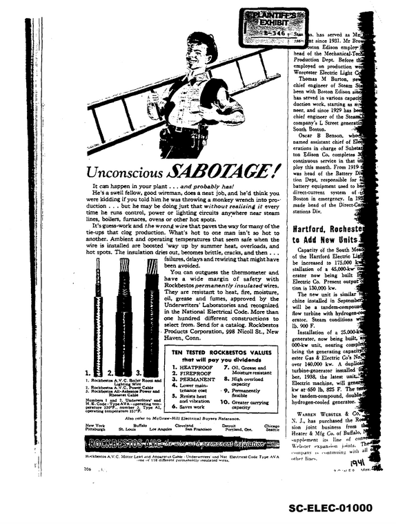
s, has served as t since 1931.
refid# K6Z2QM2kbpvL7g0KEXajRBqRX1 page
1 r.zwr C:."
refid# JrXrpE4dy7nv4DEbxQ6563ddO2 pages
PGq/Vt i, F'C* - S'r/l'*-v*ts >> * ' '" ' ' ", '
refid# Nevkav8x8BKnE0yGzkweVLa2E5 pages
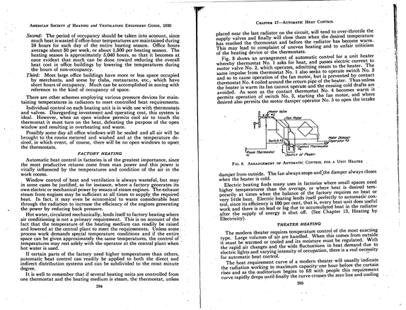
American Society of Heating and Ventilating Engineers Guide, 1930 Second: The- period of occupancy should be taken into account, since much heat is wasted if office-hour temperatures are maintained during. 24 hours for each day of the entire heating season.
refid# 91Xm18kM1VpmkQ2wxpz9Vq7x31 page
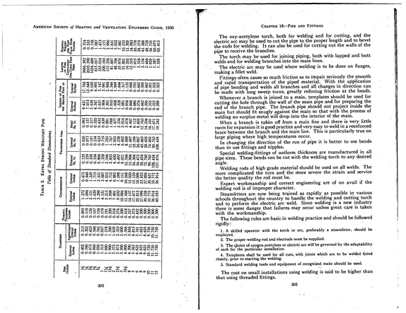
American Society of Heating and Ventilating Engineers Guide, 1930 T a b le 2.
refid# zd59QkBa4KzxDQZ72xB5Ewyj31 page
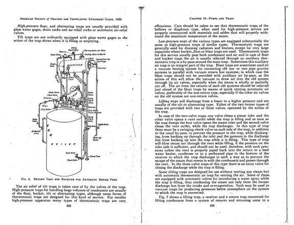
American Society of Heating and Ventilating Engineers Guide, 1930 High-pressure float, and alternating traps are usually provided with glass water gages, drain cocks and air-relief cocks or automatic air-relief valves.
refid# MM4zznJDmYgoqrxyemQM7ko1V1 page
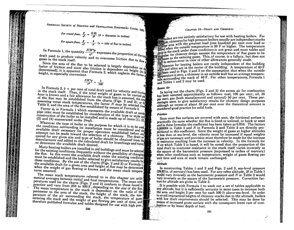
American Society of Heating and Ventilating Engineers Guide 4For round flues. - - ds (d - diameter in inches) 1931 For squareflues, (.s = side of flue in inches) In Formula 1, the quantity --NW--2*- expresses the proportion of the to draft used to produce velocity and to overcome friction due to fl0w gases in the stack itself.
refid# 932vrdnno3bjxx4q077JZYrRp1 page
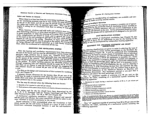
of andAmerican Society Heating Ventilating Engineers Guide m Inlets and Outlets in General *1931 When there is no heat loss from the room being ventilated, the em* air for ventilating purposes may be at very nearly the same temper ' as the air in the room, and the air may be moved across the room1 * the inlets and outlets may be opposite each other.
refid# g2nLNG7R8R6xxpLB6er3KXkVV1 page
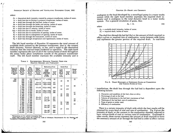
American Society of Heating and Ventilating Engineers Guide, 1932 where Dt -- theoretical draft intensity created by pressure transformer, inches of water. hi = draft loss due to friction in pressure transformer, inches of water. hF = draft loss through the fuel- bed, inches of water. hB = draft loss through the boiler and setting, inches of water. hBr = draft loss through the breeching, inches of water. hv = draft loss due to velocity, inches of water.
refid# aB4pDb4v2reOQMMJb1vXaeDRM1 page
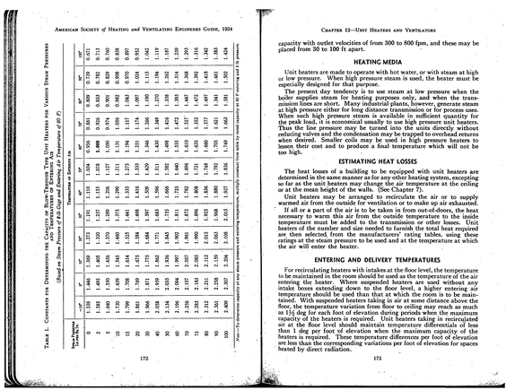
American Society of Heating and Ventilating Engineers Guide, 1934 Note.-- T o determ ine capacity a t any steam pressure and entering tem perature, m u ltip ly constant fro m table by rated capacity a t 00 F entering and 2 lb pressure.
refid# 6BZbDOBz6R99ve3v9EwRXMLYE1 page
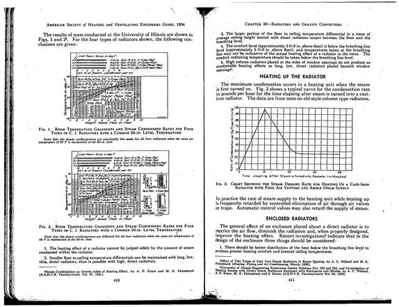
\ American Society of Heating and Ventilating Engineers Guide, 1934 The results of tests conducted at the University of Illinois are shown in Figs. 1 and 2s.
refid# XORe0LK1xqGZQmgmqzKb76orR1 page
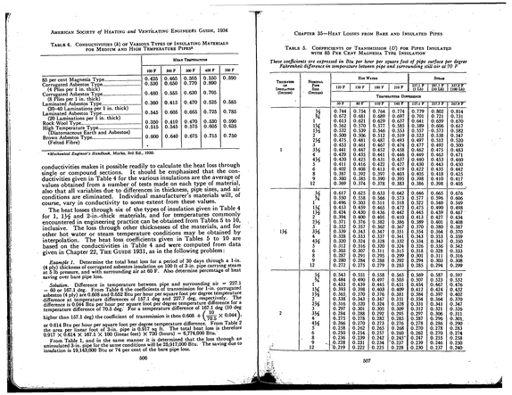
American Society of Heating and Ventilating Engineers Guide, 1934 Table 4.
refid# 0gm31oQ90wdvykXRkoVv5nDzb1 page
American Society of Heating and Ventilating Engineers Guide, 1935 So!
refid# aX8VwMjbgevQDOoLap6wLrMe1 page
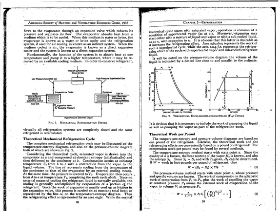
American Society of Heating and Ventilating Engineers Guide, 1936 flows to the evaporator through an expansion valve which reduces its pressure arid regulates its flow.
refid# 7OLbRgZ29m9R8wRLkNw3RGaGa1 page