Refine
Estimated Years UndatedClear
92,592 results foundRefine Search
refid# 0LkOeEaOpMvng5MDR4vDqBn1O1 page
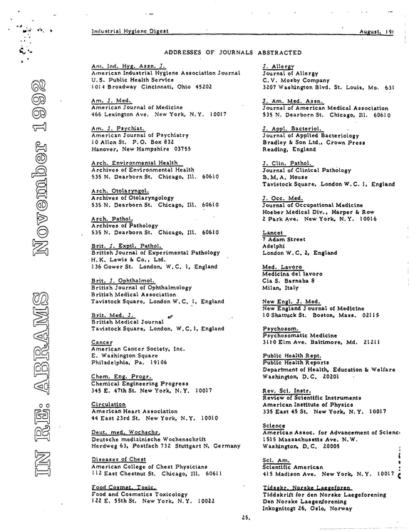
Industrial Hygiene Digest August, 191 19 ADDRESSES OF JOURNALS ABSTRACTED Am.
refid# 65v6OqkK52L2w2jN0Edoq9zMo1 page
<?
refid# DDgMX7LKNVK7vvbrEvper2bN51 page
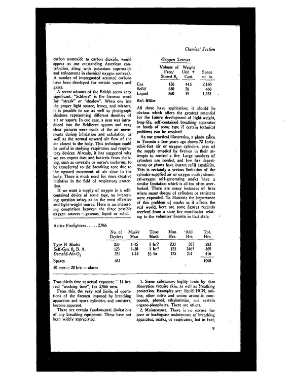
Chemical Section carbon monoxide to carbon dioxide, would appear as one outstanding American con tribution, along with potassium superoxide and refinements in chemical oxygen sources).
refid# QqmXZRqqXXDZ0N9j5J0MzOQ81 page
THE CAFETERIA THAN THE OTHERS CAN YOU CONTROL THIS PROBLEM'* HOW Several accidents have occurred in YOUR DEPARTMENT RECENTLY, APPARENTLY UNRELATED IN ANY WAY ONE VICTIM DIDN'T KNOW THE SAFE PRACTICE, ANOTHER TOOK A CHANCE BECAUSE HE WAS IN A HURRY, ANOTHER WAS INJURED WHEN A PIECE OF STOCK FELL OFF A TRUCK SOME MEN ARE BEGINNING TO FEEL THAT THE SAFETY PRO GRAM DOES NOT AMOUNT TO MUCH WHAT ACTION WILL YOU TAKE?
refid# 9MXv0X9dqaY4DyB6mQxKV2yL1 page
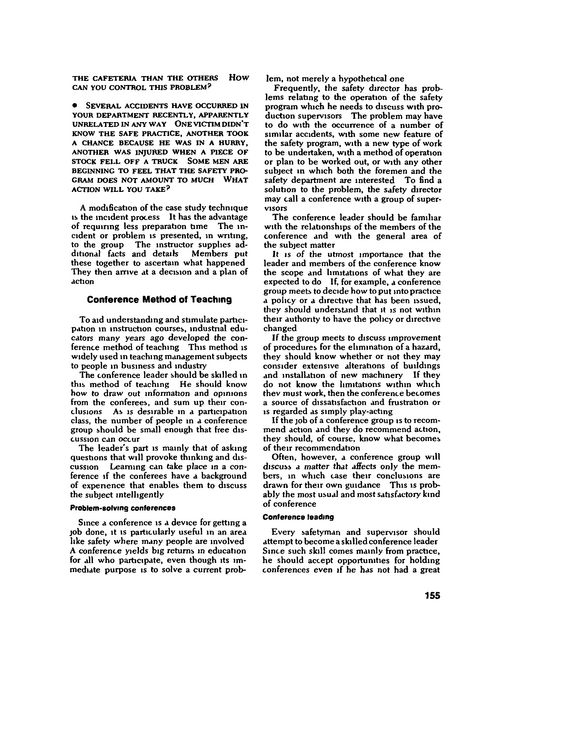
Direct experience is the best teacher Looking, listening, smelling, tasting, touch ing, and manipulating stamp realism and meaning into a communication, and make a training program a learning program These direct experiences frequently cannot be used because of practical considerations -- lack of time, money, or skill The communicator must, therefore, use more abstract means -- sometimes contrived, reconstructed, or simulated Audio-visuals are more than mere aids to communication, they are the medium of com munication itself Hence the name, "audio visual media " Effectiveness of Audio-Visual Media Fic 10-1 --Direct, actual experience "rings the bell " In measuring the impact of a presentation, the more concrete the medium of communication is, the more effective it is "Audio-visuals" encompass several dozen communications tools, ranging from purely audio aids (such as recordings and amplifying systems) to purely visual aids (such as silent films and posters) The bulk, of course, depend on both sound and sight Audio-visuals serve as a communications media for transmitting messages used to in form, persuade, inspire, and entertain people, and to solve problems They are the bndge through which a message travels between a sender and a receiver--between safetymen and management, between safetymen and workers, between management and workers and safetymen When a communications gap exists, it is usually not because there is nothing to say, it is usually because the right message did not get to the right person m the right way One should be aware of the range of audio visual resources and their appropriateness both to transmitting the message content and to appealing to and reaching the other person or the audience Figure 10-1 rates various communications media on a relative scale of concrete-toabstract experience The more concrete the communication, the more effective it is Mere words and sentences, whether spoken or written, not only provide relatively little meaning, but can often be misconstrued by the other person or persons Designing a communication, or a training program, to take advantage of more concrete resources, as they are needed, takes more ability than merely knowing the subject matter It de mands an ability to use audio-visual media effectively, and to know when each can be most effective Another advantage for using audio-visual media is that it is estimated that about 90 per cent of learning takes place through simul taneous use of seeing and hearing In ad dition to this reason, both management and workers are exposed to movies and television constantly, and they actually expect the use of audio-visual media Frequently, too much is expected of audio visual materials Just having an audio-visual available is not sufficient justification for This chapter was revised by A M Baltzer, based on reviews by selected members of the National Safety Council 217
refid# nmLM8deR1OgqY6vGo6kwM9o6X1 page
Because this chapter discusses reporting and recording accidents and injuries accord ing to ASI Standard Z16 1, the discussion is limited to disabling injuries It should be kept in mind, however, that much can be learned from reports of accidents which re sult in minor injuries, or only m property damage An investigation of these minor injuries and accidents will, in many cases, prevent a recurrence with more senous con sequences Accident Records Records of accidents are essential to effi cient and successful safety work just as rec ords of production, costs, sales, and profits and losses are essential to efficient and suc cessful operation of a business Records supply the information necessary to transform haphazard, costly, ineffective safety work into a planned safety program that controls the specific conditions and acts that cause acci dents Records are the foundation of a scientific approach to accident prevention The basis for such records is contained in two ASI standards Z16 1, ASI Standard Method ofRecording and Measuring Work In jury Experience, and Z16 2, ASI Standard Method of Recording Baste Facts Relating to the Nature and Occurrence of Work Injuries (Copies of the Standards may be obtained from the American Standards Institute) ASI Standard Z16 1 presents the standard method for classifying and recording injuries and for computing injury rates ASI Stand ard Z16 2 provides a standard method for re cording and classifying the key facts in work injuries and a recommended procedure for analyzing accidents on this basis The discussion on injury rates in this chapter interprets the provisions of Standard Z16 1 Details on how rates are calculated are given later in this chapter under "Formulas for Rates " The procedure recommended in Standard Z16 2 is discussed and illustrated in Chapter 12, "Accident Investigation, Analysis, and Costs " Use of records When kept in accordance with the standard method, records (a) provide the safety direc tor with the means for an objective evaluation of his safety program, (b) identify high-rate plants or departments, and (c) provide infor mation on the accident causes which contrib ute most to high injury rates More specifically, the records may be used to 1 Create interest in safety among super visors by furnishing them with information about the accident experience of their departments 2 Determine the principal accident sources and provide supervisors and safety com mittees with information about the most frequent unsafe practices and unsafe con ditions so that their efforts may be concen trated where the largest reductions m accidents can be effected 3 Judge the effectiveness of the safety pro gram by showing whether the accident experience is getting better or worse, and by providing comparisons with the ex perience of similar organizations Steps In record keeping There are five important steps m develop ing adequate information about employee accident experience 1 Obtain a report on every injury, including medical treatment cases 2 Classify and record each injury according to Standard Z16 1 3 Prepare a monthly or other periodic sum mary report showing injury rates and the circumstances and causes of the accidents which resulted m the injuries 4 Analyze periodically the circumstances and causes of the accidents 5 Make an annual report to the National Safety Council on forms provided by the Council, for comparison with the records of similar organizations Nearly all states require that reports be prepared for work injuries The types of reports and the tvpes of injuries reported vary, depending on the laws and rulings in the different states It must be emphasized, This chapter was revised by the Statistics and lndustnal Department Staffs, based upon reviews by selected members ofthe National Safety Council 243
refid# 3Np6Onbog4LpY40zZw7j5N2Xa1 page
Boilers and Unfired Pressure Vessels rupturing pressure of the disk so that it is necessary either to replace it or clean it with a solvent The condition of these disks should be checked frequently to see that they are clear It must be remembered that when the disk ruptures, all pressure is relieved from the vessel This could result m complete loss of product or spoiled in-process matenal A rupture disk must function within 5 per cent of its specified bursting pressure at a specified temperature Disks may be in stalled between a spnng-Ioaded safety or relief valve and the pressure vessel in order to prevent unnecessary corrosion of the valve and to prevent it from becoming plugged by the contents of the vessel These multiple installations must be in accordance with the ASME Code, Section VIII Various designs of rupture disks are avail able Vacuum breakers.
refid# ppBgvwrNqK044zo9YrZqx3nYk1 page
install bumper strips at the level of truck platforms and truck push bars (Fig 21-7) Strips should be made of oak, ash, hickory, or similar tough, resilient wood and should be at least 1V& in thick, and 2 in thick where heavy trucks are used Steel channels are also effective Strips should be wide enough to match all heights of platforms and pushbars of trucks that are transported in the elevator Painting the inside of the car a flat black, from the floor to the top of the upper guard strip, will make bumps and scrapes less con spicuous If the sides above the top stnp are painted aluminum, the high reflectance value of the paint will help overall illumination Top covers Freight elevator cars may have either solid or openwork top covers If open work is used, the "Elevator Code" requires that the openings be small enough to reject a ball I VS in in diameter, some companies, however, recommend 44-in openings Wire mesh is recommended for openwork covers, because it combines maximum strength with minimum weight and offers little interference with light and air Not less than No 10 gauge steel wire should be used The cover should be strong enough to sustain a load of 300 pounds on any square area 2 ft on a side or of 100 pounds applied at any one point In the top of every elevator car there should be an emergency exit of at least 400 sq m area, providing an unobstructed passageway to permit easy escape if the car becomes stalled between floors or some other emer gency anses The exit cover should open outward and be so hinged or attached that it can be opened easily from the top of the car only A heavy cover should be counterweighted or divided into several hinged sections, which should be kept down except when being used Doors or gates To conform to "Elevator Code" requirements for new installations, a car door or gate must be provided at each entrance to the car If the elevator is elec trically operated, the car door or gate should have electnc contacts that will prevent move ment of the car unless the door or gate is within 2 in of the fully closed position On existing elevator cars having more than one opening, it is recommended that each entrance be equipped with a car gate The gate should be provided with a contact to prevent its being opened when the car is in motion When closed, the gate should guard the full width and height of the opening (except for vertically sliding gates, which should extend from a point not more than 1 in above the car floor to a height of at least 6 ft) Collapsible gates, when fully expanded, should reject a ball 3 in m diameter They should have convenient handles with guards for protection of the operator's fingers Floors of cars should be kept in good con dition Ordinary metal sheets should not be used for surfacing or repairing floors because they soon become smooth and slick In time, even sheet metal with raised surface markings may wear smooth and then should be replaced Neither the edge of the car platform nor the edge of the landing should be permitted to become slippery or badly worn Cast iron and steel sills at such points are slipping hazards unless provided with anbslipsurfaces Abrasive strips or welded beading may be applied to eliminate slippenness Loads The safe working load (or rated capacity) of an elevator includes a safety factor, but nevertheless it should not be ex ceeded The rated safe load should be indi cated by a conspicuous sign Metal signs with stamped, etched, or raised letters and figures not less than 54-in high are satisfactory for passenger elevators, and with 1-in high letters and figures for freight elevators To find the maximum number of passengers allowable under emergency conditions, common practice is to divide the rated safe capacity load in pounds by 150 Lighting.
refid# Yj31zo7v5qkR3oEyzr4Xpkn6O1 page
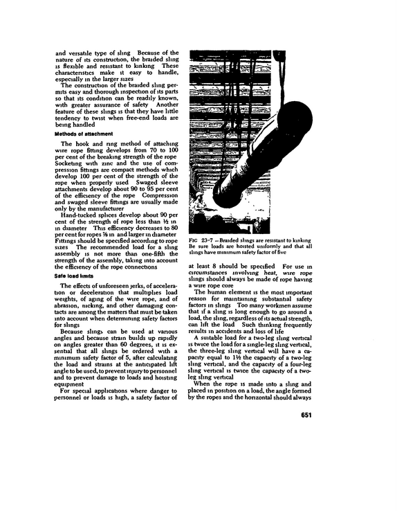
and versatile type of sling Because of the nature of its construction, the braided sling is flexible and resistant to kinking These characteristics make it easy to handle, especially m the larger sizes The construction of the braided sling per mits easy and thorough inspection of its parts so that its condition can be readily known, with greater assurance of safety Another feature of these slings is that they have little tendency to twist when ftee-end loads are being handled Methods of attachment The hook and ring method of attaching wire rope fitting develops from 70 to 100 per cent of the breaking strength of the rope Socketing with zinc and the use of com pression fittings are compact methods which develop 100 per cent of the strength of the rope when properly used Swaged sleeve attachments develop about 90 to 95 per cent of the efficiency of the rope Compression and swaged sleeve fittings are usually made only by the manufacturer Hand-tucked splices develop about 90 per cent of the strength of rope less than Vi in m diameter This efficiency decreases to 80 per cent for ropes % in and larger m diameter Fittings should be specified according to rope sizes The recommended load for a sling assembly is not more than one-fifth the strength of the assembly, taking into account the efficiency of the rope connections Safe load limits The effects of unforeseen jerks, of accelera tion or deceleration that multiplies load weights, of aging of the wire rope, and of abrasion, nicking, and other damaging con tacts are among the matters that must be taken into account when determining safety factors for slings Because slings can be used at vanous angles and because strain builds up rapidly on angles greater than 60 degrees, it is exsenbal that all slings be ordered with a minimum safety factor of 5, after calculating the load and strains at the anticipated lift angle to be used, to prevent injury to personnel and to prevent damage to loads and hoisting equipment For special applications where danger to personnel or loads is high, a safety factor of at least 8 should be specified For use in circumstances involving heat, wire rope slings should always be made of rope having a wire rope core The human element is the most important reason for maintaining substantial safety factors in slings Too many workmen assume that if a sling is long enough to go around a load, the sling, regardless of its actual strength, can lift the load Such thinking frequently results in accidents and loss of life A suitable load for a two-leg sling vertical is twice the load for a single-leg sling vertical, the three-leg sling vertical will have a ca pacity equal to lVi the capacity of a two-leg sling vertical, and the capacity of a four-leg sling vertical is twice the capacity of a twoleg sling vertical When the rope is made into a sling and placed in position on a load, the angle formed by the ropes and the horizontal should always 651
refid# NGoL3JGjLbMNLzGVGjja3qjbp1 page
Machine Tools fence, usually of iron pipe sections, should be installed Such fencing should conform to the state code or the specifications of theASI Standard A121, Safety Requirements for Floor and Wall Openings, Ratlings and Toe Boards The operator should never attempt to bghten the work or the tool, caliper or measure the work, feel the edges of the cutting tool, or oil the mill while it is m operation, nor should he nde the table while it is in motion, except that on some large mills, like those used for boring turbine castings, the operator may have to nde the table in order to observe the progress of the work In such cases, he should always be certain that no portion of his body will come in contact with a sta tionary part of the mill Steps or stairs which provide access to the machine or to the work should have a pitch of not more than 50 degrees and should have nonslip treads Stairs with four or more nsers should be provided with a standard handrail 34 in above tread center Milling Machines Milling--machining a piece of metal by bringing it into contact with a rotating multiedged cutter--is done by horizontal and vertical milling machines, by gear hobbers, profiling machines, circular and band saws, and a number of other types of related machines About two of every three milling machine accidents occur when operators unload or make adjustments Other causes of injuries include 1 Failure to draw the job back to a safe distance when loading or unloading 2 Using a jig or vise which prevents close adjustment of the guard 3 Placing the jig or vise-locking arrange ment in such a position that force must be exerted toward the cutter 4 Leaving the cutter exposed after the job has been withdrawn 5 Leaving hand tools on the worktable 6 Failure to clamp the work securely 7 Reaching around the cutter or hob to remove chips while the machine is in motion 8 Removing swarf by hand instead of with a brush 9 Adjusting the coolant flow while the cutter is turning 10 Calipering or measuring the work while the machine is operating 11 Using a rag to clean excess oil off the table while the cutter is turning 12 Wearing gloves, ties, or loose clothing 13 Using cutters incorrectly dressed 14 Stonng cutters incorrectly 15 Attempting to remove a nut from machine arbor by applying power to the machine 16 Striking cutter with hand or arm while setting up or adjusting stopped machine Basic milling machines Regardless of the classification, direction of movement, or special attachments which make varied operations possible on a milling machine, the safeguarding requirements are basically the same To guard the cutter, one of several methods should be employed (Fig 26-7) The hand-adjusting wheels for quick or automatic traverse on some models should be mounted on the shaft by either clutches or ratchet devices so that the wheels do not revolve when the automatic feed is used, or else the wheels should be provided with re movable handles with compression springs so that the handles cannot remain m the wheels unless held in place by the operator The horizontal milling machine should have a splash guard and pans for catching thrown cutting lubricant or lubricant running from the tools The lubricant should be directed on the work in such a way that the distribution setup will not be drawn into the cut bv means of the cutter rotation When possible, all cuts should be made into the travel of the table, rather than away from the direction of travel Metal saws A circular saw for cutting cold metal stock should have a hood guard at least as deep as the roots of the teeth, and the guard should 756
refid# 1QO7rXzeBNE9D1O9kgeqq96Rj1 page
Woodworking Machinery A circular saw should be stopped when the operator leaves it It is not sufficient to cut the switch and walk away since amputations have been caused by saws still idling with the power off An electric brake attached to the motor arbor offers fast, positive stopping ac tion Another effective method is shown in Fig 27-4 Sawdust slivers should be cleared away from a saw with a brush or a stick, never with the hands Under no circumstances should either the saw guard or the fence gauge be adjusted while the saw is running Parallel setting of the gauge is of particular importance To enable the operator to set the gauge without removing the guards, it is good prac tice to mark the top of the saw table with a permanent, distinctive line directly m front of and in line with the saw Circular saw blade maintenance The characteristics and condition of cir cular saws have an important bearing on the safety of the men who use them Saw manu facturers have published much valuable in formation on the selection, use, and care of saws The circular saw is a thin disk of metal that revolves rapidly as the result of power applied at its center At the same time, since resistance is applied to its nm at one point at a time, that point on the nm where the resis tance is applied tends to drag That portion of the nm forward of the cut tends to run ahead, thus producing a stretching action, and that portion which has not yet reached the cut tends to be compressed In designing, building, and tensioning a saw, the maker gives it enough ngidity and tensile strength to withstand these forces without harmful distortion Altenng a saw from its onginal design, operating it at other than its rated speed, or changing its balance or tension seriously affects its efficiency and safetv Some faults of circular saws that may cause difficult, unsatisfactory operation are SAW OUT OF round If some teeth are longer than others, the long teeth do most of the work An unequal strain is thus imposed on the saw, which may cause it to run out of line, to heat up, and to warp Saw not straight (out of plane) Lumps or warps can be checked with a straightedge the length of the diameter of the saw Improper hook or pitch of teeth Ripsaw and cutoff teeth differ in design for different kinds or wood and for different pur poses Combination saws may be used for both crosscutting and ripping Improper OR uneven set A circular saw has to cut a kerf thicker than the blade to give clearance which permits the saw to pass through the wood Set or swage is given the teeth by bending alternate teeth nght and left or by spreading the point of every tooth so that each is slightly wider than the saw Cracked blades Saw blades should be inspected for cracks each time the teeth are filed or set Some cracks are so small that they may be invisible to the naked eye The Magnaflux method for testing saw blades is extensively used If cracked saw blades are continued in service, the crack frequently grows larger and eventually may cause par tial fragmentation Most cracks start in the gullets As soon as a crack is visible to the naked eye, the blade should be removed from service The blade usually can be repaired either by weld ing the crack or by slotting the saw to remove the material on both sides of the crack and then making other slots to balance the blade Whatever method is used, the saw blade must be retensioned after repairs have been made This is a job for a sawsmith, and un less the company has the services of such a man, the blade should be repaired by the manufacturer Excessive heat and vibration cause saw blades to crack To prevent cracking, these precautions should be followed 1 The sav\ blade should be tensioned for the speed at which it vi ill operate Other wise, the blade will wobble and vibrate and, as a result, will heat, expand, and crack 2 The teeth must have sufficient clearance (setor hollow grinding) to prevent burning, with consequent heating and cracking 788
refid# x53njne3bmkkwXyjXg7Ddqx001 page
Types A SPOT weld is made by applying heat and pressure at one point, usually on overlapped parts A SEAM weld is a senes of overlapping spot welds, spaced close enough to make a single, continuous joint A projection weld is a spot weld made between two parts, one or both of which have an embossment or projection, which localize the welding heat and pressure Flash and upset welds are welds made by butting two parts together and forming a weld for the full cross-section of the con tacting faces In flash welding, pressure is applied after heating is substantially com pleted In upset welding, pressure is main tained throughout the welding cycle Percussion welding is similar to flash and upset welding except that the welding heat is obtained from a rapid discharge of stored electrical energy Resistance welding machines are operated manually, semiautomatically, and auto matically (Fig 31-5) Fixed installation is most common, but portable machines are also available They use manual, electrical, me chanical, pneumatic, or hydraulic power to apply pressure They are often equipped with intricate control and timing devices Modem mechanical handling devices for the work add to their efficiency Expert main tenance is required for these welding matchines, even though they may be operated by unskilled labor Power supply Resistance welding usually employs 60Hertz alternating current which is fed to the primary of the water-cooled welding trans former The input can vary from 150 to 10,000 amp, at 240, 440, or 550 volts The output, at the secondary of the transformer is a low voltage (max 30 volts) and high current (up to 200,000 amp) used for welding The welding current is sometimes fur nished by the "stored energy" type of equip ment, m which energy is built up and stored either in capacitors or in a combination trans former-reactor during the nonwelding period, and then is discharged to form the weld This process involves low currents and high volt ages, which must be guarded against To facilitate servicing the equipment, a safety type disconnecting switch or a circuit breaker of the correct rating for opening supply circuits should be installed near the welding machine Permanent injuries, and several fatalities have been caused by neg lecting to use the line-disconnecting switch before making adjustments The use of single-pole primary circuit breakers and elec tronic contactors which leave one line to the welder "hot" makes this precaution im perative Current and timing controls are of two types, mechanical and electronic If worn parts throw the mechanical control out of synchronism with the current and voltage waves, transients may cause severe damage to the equipment Synchronism should be carefully maintained, particularly on highpower equipment The electronic controls are placed m the primary circuit and involve high voltages which must be guarded by proper insulation, lockouts, and safety switches All electrical work should conform to ap plicable codes Cables The high current of the primary circuits (up to 10,000 amp) in resistance welding does not permit the use of plugs except for control circuits, usually 120 volts or less Power lead terminals should be securely and perma nently attached with screws or bolts for the duration of service The magnitude of the secondary welding current is such that the cables for a portable welding machine must be heavy Even with sizes from 200,000 to 1,000,000 circular mils, copper losses are high and in many instances water cooling is required, especially for high production portable, as well as multiple-spot station, welding machines The length of these cables vanes from 1 to 14 ft, the latter being the maximum considered reasonably economical The covenng for the cable used with a portable welding machine is thick, high tensile rubber Abuse of the cables for resistance welding is severe The production requirements de mand the utmost of the cable matenals used, and even the best cables need frequent re- 931
refid# 58E10JqkGjekgErLRo3zVbX51 page
cleaning procedures and other precautions Small tanks and drums should be cleaned and steamed in an open-faced building with ample roof ventilation It is even preferable to clean them in an outside area free from ignition sources Pipes and nozzles should be electrically bonded to containers being steamed Covers, plugs, and valves should first be removed and the tank or drum permitted to drain into a container The inside should be examined for rags, waste, or other debris that might interfere with draining and retain flammable vapors Only lights approved for use in the National Electrical Code Class I, Division I, Group D hazardous locations should be used for this inspection, see expla nation m the previous chapter Mirrors can sometimes be used to reflect daylight inside for this purpose Steaming.
refid# Eva98Zv9YLK27yqQdEV50dq6L1 page
breakers, using wrong fuses, bypassing fuses, and installing equipment without authoriza tion Electrical installations and all electrical equipment should be periodically inspected and tested to assure continued satisfactory performance and to detect deficiencies Smoking Carelessly discarded cigarettes, pipe em bers, and cigars are a major source of fire Although it might be desirable to eliminate smoking completely in a plant, such a rule is difficult to enforce It is better to allow smok ing at specified times and in a safe place where supervision can be maintained than to have it done surreptitiously in out-of-theway places Smoking shofild be prohibited in wood working shops, textile mills, flour mills, grain elevators, and places where flammable liq uids or combustible products are manufac tured, stored, or used Even m these opera tions, enclosed or removed areas can be set aside to allow workmen to satisfy their smoking needs in a safe manner "No smoking" areas should be marked with conspicuous signs and their exclusive use ngidlv enforced everyone, including super visors and visitors, should adhere to the reg ulation It mav be necessary to use more than signs to draw attention to the "no smok ing" areas Lines drawn on the floor or illu minated barriers placed around areas or proc esses have been effective In manv high-hazard occupancies, smoking is permitted in special fire-safe rooms or during periods when there is no exposure In such cases, instructions or warning signs to that effect should be posted Where the exposure is severe, emplovees should even be prohibited from carrying matches, lighters, and sometimes smoking material of any kind into the danger areas In any case, the use of "safety" matches should be encouraged, and smoking should be allowed only in fire-safe areas Where carrying matches into the plant is prohibited, special lighters should be provided in smok ing rooms Even in plants where there is little fire hazard, employees should be encouraged to discard matches and smoking materials in a safe container rathei than on the floor This practice will discourage employees from throwing matches and cigarettes into places which may not be free of hazards Fnction Excessive heat generated by friction causes a very high percentage of industrial fires.
refid# XkQ04kQ7Owbj36womzryMMjB1 page