Refine
Estimated Years UndatedClear
267,355 results foundRefine Search
Types of guards To eliminate the dangers involved in ma chine operation, either guards may be built and installed over the hazardous areas or the equipment may be redesigned to have no ex posed dangerous parts The modern lathe is a good example of machinery made safe through improved de sign Its motor drive and gear box are en closed so that line shafts, pulleys, and belts are dispensed with The modern power press, in which all the working parts with the excep tion of the slide are enclosed, is another good example Tvpes of guards which arc used to make machinery safe include the fixed guard, the interlocking guard, and the automatic guard These may be added after a machine is in stalled, or purchased built-in by the manu facturer The fixed guard is considered preferable to all other types and should be used m every case unless it has been definitely determined that this type is not at all practicable The fixed guard at all times prevents access to the dangerous parts of the machine Fixed guards may be adjustable to accom modate different sets of tools or various kinds of work Once adjusted, they should remain "fixed," and there should be no movement nor detachment of them Some fixed guards are installed at a distance from the danger point in association with re mote feeding arrangements which make it unnecessary for the operator to approach the danger point A table of the safe distance of a guard from the danger point and the permissible size of openings in a fixed guard is given m the "De signing Pomt-of-Operation Guards" section of this chapter Examples of fixed guards are found on power presses, sheet leveling or flattening machines, milling machines, gear trains, drill ing machines, and guillotine cutters Interlocking guards.
refid# Byg32oryBXk1wJyOqgoD8GaOk1 page
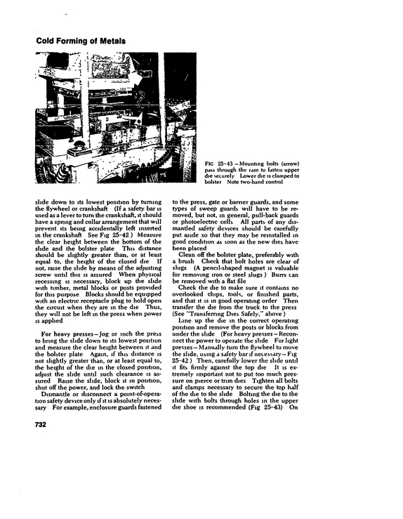
Cold Forming of Metals FlC 25-43 --Mounting bolts (arrow) pass through the ram to fasten upper die securely Lower die is clamped to bolster Note two-hand control slide down to its lowest position by turning the flywheel or crankshaft (If a safety bar is used as a lever to turn the crankshaft, it should have a spring and collar arrangement that will prevent its being accidentally left inserted in the crankshaft See Fig 25-42 ) Measure the clear height between the bottom of the slide and the bolster plate This distance should be slightly greater than, or at least equal to, the height of the closed die If not, raise the slide by means of the adjusting screw until this is assured When physical recessing is necessary, block up the slide with timber, metal blocks or posts provided for this purpose Blocks should be equipped with an electric receptacle plug to hold open the circuit when they are in the die Thus, they will not be left in the press when power is applied For heavy presses--Jog or inch the press to bring the slide down to its lowest position and measure the clear height between it and the bolster plate Again, if this distance is not slightly greater than, or at least equal to, the height of the die m the closed position, adjust the slide until such clearance is as sured Raise the slide, block it m position, shut off the power, and lock the switch Dismantle or disconnect a point-of-operation safety device only if it is absolutely neces sary For example, enclosure guards fastened to the press, gate or barrier guards, and some types of sweep guards will have to be re moved, but not, in general, pull-back guards or photoelectric cells All parts of any dis mantled safety devices should be carefully put aside so that they may be reinstalled m good condition as soon as the new dies have been placed Clean off the bolster plate, preferably with a brush Check that bolt holes are clear of slugs (A pencil-shaped magnet is valuable for removing iron or steel slugs ) Burrs can be removed with a flat file Check the die to make sure it contains no overlooked chips, tools, or finished parts, and that it is in good operating order Then transfer the die from the truck to the press (See "Transferring Dies Safely," above ) Line up the die in the correct operating position and remove the posts or blocks from under the slide (For heavy presses -- Recon nect the power to operate the slide For light presses --Manually tum the flywheel to move the slide, using a safety bar if necessary--Fig 25-42 ) Then, carefully lower the slide until it fits firmly against the top die It is ex tremely important not to put too much pres sure on pierce or trim dies Tighten all bolts and clamps necessary to secure the top half of the die to the slide Bolting the die to the slide with bolts through holes in the upper die shoe is recommended (Fig 25-43) On 732
refid# b5oKgLJMdDd1jy1wa9eoM4R11 page
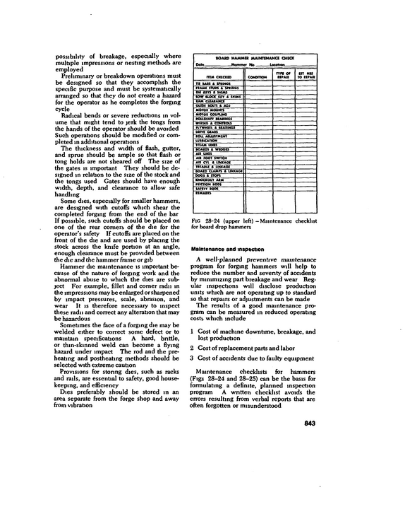
possibility of breakage, especially where multiple impressions or nesting methods are employed Preliminary or breakdown operations must be designed so that they accomplish the specific purpose and must be systematically arranged so that they do not create a hazard for the operator as he completes the forging cycle Radical bends or severe reductions in vol ume that might tend to jerk the tongs from the hands of the operator should be avoided Such operations should be modified or com pleted in additional operations The thickness and width of flash, gutter, and sprue should be ample so that flash or tong holds are not sheared off The size of the gates is important They should be de signed m relation to the size of the stock and the tongs used Cates should have enough width, depth, and clearance to allow safe handling Some dies, especially for smaller hammers, are designed with cutoffs which shear the completed forging from the end of the bar If possible, such cutoffs should be placed on one of the rear comers of the die for the operator's safety If cutoffs are placed on the front of the die and are used by placing the stock across the knife portion at an angle, enough clearance must be provided between the die and the hammer frame or gib Hammer die maintenance is important be cause of the nature of forging work and the abnormal abuse to which the dies are sub ject For example, fillet and comer radii in the impressions may be enlarged or sharpened by impact pressures, scale, abrasion, and wear It is therefore necessary to inspect these radii and correct any alteration that may be hazardous Sometimes the face of a forging die may be welded either to correct some defect or to maintain specifications A hard, brittle, or thin-skinned weld can become a flying hazard under impact The rod and the pre heating and postheating methods should be selected with extreme caution Provisions for storing dies, such as racks and rails, are essential to safety, good house keeping, and efficiency Dies preferably should be stored in an area separate from the forge shop and away from vibration Dote BOARD HAMMER MAINTENANCE CHECK Hummer No targfmw item CHECKED TIE BARS 8 SPRINGS NAME STUDS A SPRINGS DU KEYS A SKIMS SOW BLOCK KCT A SHUNS RAM CLEARANCE GUIDE BOLTS A ADJ MOTOR MOUNTS MOTOR COUPLING ROUSHAFT BEARINGS WIRING A CONTROLS FLYWHEEL A BEARINGS DRIVE GEARS ROU ADJUSTMENT LUBRICATION STEAM LINES BOARDS A WEDGES Alt LINES AIR FOOT SWITCH AIR CU A LINKAGE TREADLE A LINKAGE BOARD CLAMPS A LINKAGE DOGS A STOPS KNOCKOUT ARM FRICTION RODS SAFETY RODS REMARKS CONDITION TYPE OP REPAIR EST HRS TO REPAIR Fig 28-24 (upper left) -- Maintenance checklist for board drop hammers Maintenance and inspection A well-planned preventive maintenance program for forging hammers will help to reduce the number and seventy of accidents by minimizing part breakage and wear Reg ular inspections will disclose production units which are not operating up to standard so that repairs or adjustments can be made The results of a good maintenance pro gram can be measured in reduced operating costs which include 1 Cost of machine downtime, breakage, and lost production 2 Cost of replacement parts and labor 3 Cost of accidents due to faulty equipment Maintenance checklists for hammers (Figs 28-24 and 28-25) can be the basis for formulating a definite, planned inspection program A written checklist avoids the errors resulting from verbal reports that are often forgotten or misunderstood 843
refid# 3eEx59yj1X5nk0Ng3vbLZzaG01 page
Local Exhaust System Low maintenance, that is, infrequent and quick servicing of the collector, is essential to keep to a minimum the exposure of the men doing the job Finally, the radioactive or highly toxic material must be concentrated during col lection to the smallest possible volume Disposal through discharge to air, water, or land in the usual manner is not permitted Incineration is often used, with the irreduc ible residue consigned to a burial ground Only a few types of collectors meet these requirements Drv cyclones are no good be cause their collecting efficiency is too low Any unit with an involved internal structure must be ruled out because of service difficul ties The reverse-jet cloth arrester with wool felt media has become almost a standard where there is no problem of temperature or corrosion Where such problems exist, the high-voltage electrostatic collector can be used Low-efficiency, low-cost filters are often used as integral parts of laboratory hoods or dry boxes m which radioactive matenals are handled They serve as scalping filters to keep high concentrations of contaminated material from entering the main exhaust system They must be followed or backed up by an ultra-high-efficiency filter or dust arrester They have limited capacity and must be changed frequently Before they are changed, they can well be sprayed while still in position with an acrylic spray to fix any radioactive dust Air cleaners for fumes and smokes Fumes come from reactions such as burn ing, sublimation, distillation, and especially the condensing of a vapor given off by a molten metal The composition of fumes mav be different from that of the parent material Lead fume, cadmium fume, zinc oxide, and iron oxide (welding fume) are typical examples Their particles are gen erally below 1 micron, so they show active Brownian movement (that is, they are fai too small to settle out), and they are re markably uniform in size Smokes are com monly organic, coming from incomplete combustion of coal, oil, wood, and other fuels They are usually dark or jet black in color, and obscure light Their particles compare in size to the particles of metal lurgical fumes The high-efficiency dust collectors already mentioned --the cloth filter, high-efficiency wet collector, and electrostatic precipitator-- are best for arresting fumes For smokes, the answer is improved combustion, or the high-voltage electrostatic precipitaloi, oi both Air cleaners for gases and vapors Vapors may be defined as the gaseous form of a material which is normally m the liquid or solid state at room temperature Gases and vapors are not particles, but are indivi dual molecules dispersed among the mole cules of the air Gases and s'apors diffuse Arresters depending on the straining action of filters or on centrifugal force are not appli cable Methods generally used are as follows Absorption.
refid# 5b3nvXVLRNRry733a1VODarRV1 page
curved type, since spaces between blades soon become filled with paint Tempered makeup air to replace air ex hausted by the booth should be supplied This is needed for any exhaust svstem, but deserves special attention here because some spray booths remove huge amounts of room air, which in turn should be supplied directly to the booth or to the area from which the air is drawn into the booth Routine and scheduled cleaning and main tenance of spray booths are a must Flam mable materials when allowed to accumulate increase the fire risk Paint in ducts also cuts down needed air flow There are several products on the market which can be used to cover the inside of the booth, either sprayed or brushed on, which successfully prevent the sticking of the overspray to the booth surfaces Some of these are easily strippable coatings In high production painting much solvent is lost by evaporation from the wet painted surfaces If these surfaces are stacked out in the shop to dry, they may present a health and fire hazard A separate ventilated area should be provided for preliminary drying of the finished materials before they are sent to the ovens for baking Where the production is not high, the ma terial can be left in the booth for preliminary drying In no instance should finished material be stacked in front of the booth so that the air flow is from the freshly finished material to the operator If the booth is used for welding, a heavy canvas curtain should be placed around the front of the booth to safeguard the eyes of others in the room from the ultraviolet rays of the welding arc Dusts from some of the materials used m metallizing are explosive if finely divided and suspended in air in a critical concentra tion When collecting dust from metalliz ing, it is sometimes necessary to provide wet dust arrester units back of the metallizing booth Fume control for electric welding Movable exhaust hoods are needed for most indoor welding applications, and are a must when welding potentially toxic materials such as lead-containing or lead-painted metals, and beryllium alloys Except for production spot welding done at some sort of fixed jig, a welder usually travels over a wide area and this necessitates some ar rangement of flexible or movable piping The hood itself can have a rectangular face with a flared section to which the duct is connected, thus giving a streamlined air flow Normally the hood is surrounded on all four edges by a 3-in flange The breadth of the face and the amount of the air flow ex hausted should be such that fumes will be removed from the welding arc over the length of weld formed during the consumption of one welding rod The capacity of the exhaust, therefore, should be sufficient to "reach" laterally over one-half the length of a weld of this distance Flexible metal duct branches or solid sections with swivel joints and counterbal ances permit easy relocating of the hood A duct branch should not be less than 3 in in diameter and should handle at least 200 cfm Larger branches and higher air flows should be used whenever possible Face velocities can exceed 1500 fpm (average) and duct velocities should assure a sufficiently high air flow into the hood to control fumes at the point of generation (usually several inches away from the hood face), as well as avoid settlement in the duct Specific figures for ventilation based on distance from weld ing arc are given in Chapter 31, "Welding and Cutting " Dust control in foundnes Foundries offer many difficult problems m dust control, particularly in the shake-out and cleaning rooms Dust at the shake-out in a hand foundry that processes small cast ings can be adequately controlled by wet methods, with the castings removed from the sand before the sand dnes out enough to form a great deal of dust In a more mechanized foundry the shake out generally can be covered by a fairly tight enclosing hood if the flasks are small enough to be handled on conveyors, the major part of the exhaust should be taken from overhead to utilize the thermal circu lation of air over the hot metal When the flasks are so large that they must be handled by cranes, a side hood on the shake-out grate is about the only possible choice unless the whole operation can be enclosed and isolated 883
refid# xdrrmEBV2zbKyoVJdMMYLxGj61 page
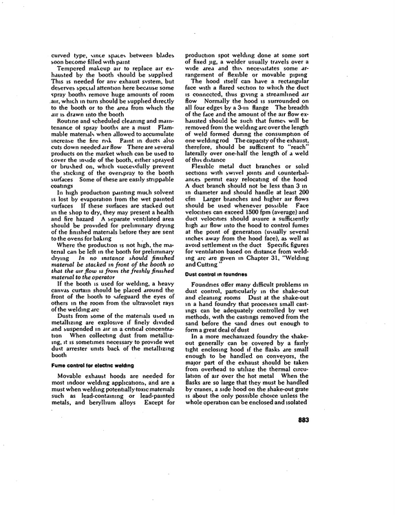
method can be used in the distributing cen ter or the tool room to check portable tools before they are issued or upon their return The test should be made between the ground ing prong on the plug and the tool frame Double-insulated tools Maintaining a good ground and making sure a man uses it properly can be, unfortu nately, a big problem Add to this the fact that some companies have not yet installed the three-blade grounded receptacle because of the easy availability of the adapter that allows the use of a two-blade receptacle In the latter case, an operator can use a portable electrical tool without connecting the adapter ground wire Sometimes, if the adapter be misplaced, a workman may even cut off the grounding connection on the port able power tool If an electric light outlet is used as a power source, the third wire may never be connected A completely safe operation, therefore, re quires regular tests to maintain a good ground, and regular checks to make sure workers are grounding electrical equipment To overcome these difficulties, portable tool manufacturers have developed another way to provide safety from electrical shock for tool users One that has gained consider able acceptance is double insulation (See discussion under "Electric tools," in previous chapter ) GROUND CLAMP Fig 33-6 -- A simple low-voltage test unit with an indicating light bulb The diagram shows a con tinuity test between the ground prong of the plug and the ground wire connection to the metal shell Courtesy Self-Insurers Service.
refid# 7VNabk31KMBawg68XgNKeqLB1 page
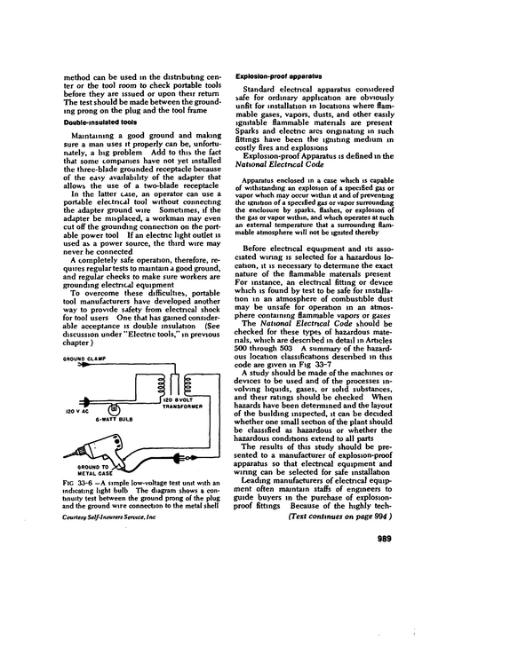
Fire Loss Control FlC 35-3 --Components of heavy timber building showing flooi training and identifvmg components of sennmill-type framing Courtesy Notional Fire Protection Association of the wooden members slows the rate of com bustion Moreover, the char which forms on wooden surfaces serves as an insulator for the wood within Noncombustible construction includes all types of structures in which the structure it self (exclusive of trim, interior finish, and contents) is noncomliustible but not fire re sistant Exposed steel beams and columns, and masonrv, metal, or asbestos panel walls, are the most common forms (Fig 35-4) Because of the tendency of steel to warp, buckle, and collapse under moderate fire exposure, noncombustible construction is relatively vulnerable to fire damage It is, therefore, most suitable for low-hazard occu pancies If quantities of combustibles are present, the structure should be protected with automatic sprinklers Ordinary construction consists of masonry exterior bearing walls, or beanng portions of exterior walls, that aie of noncombustible construction Interioi flaming, floors, and roofs are made of wood oi other combustible material whose "bulk" is less than that re quited foi heav\ timber construction 11 floor and roof construction and their supports have a one-hour fire-resistance rat ing, and all openings through floors (including stairways) are enclosed with partitions having a one-hour fire-resistance rating, then it is known as "protected ordinary construction " 1050
refid# G6J5Qyor5yGq8yJkg6qROx8nV1 page
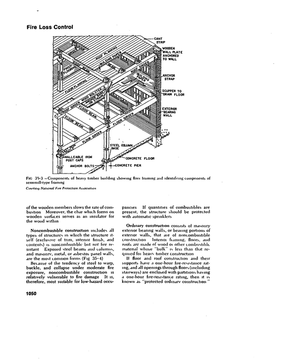
to some chemicals but satisfactorily stop splashes and protect the eyes Whereas fogging occurs on both glass and plastic, it usually takes longer for plastic to fog Frames should be rigid enough to hold the lenses in the proper position m front of the eyes Most manufacturers make spectacles with a bridge designed to fit the majority of faces Frames should be constructed of cor rosion-resistant material that will neither ir ritate nor color the skin The simpler the design, the easier the goggle is to clean Cup goggles should have cups large enough to protect the eye socket and to distribute the impact over a wide area of the facial bones Cups should be flame-resistant (as should be the frames), corrosion resistant, and nonimtating to the skin If lenses are to be exposed to pitting from grinding wheel sparks, a transparent and durable coattng may be applied to them Welding lenses should be protected by a cover lens of glass or plastio Lenses must not have appreciable distor tion or pnsm effect ASI Standard Z87 and Federal Specification GGG-G-501b (Federal Standard Stock Catalog) limits the non parallelism between the two faces to Vis prism diopter (4 minutes of arc) and both the re fraction m any meridian and the difference in refraction between any two meridians to '/is diopter Both when supported in the eye cups of goggles and when supported on a rubber gasket on a wood tube, lenses are required to withstand the impact test described earlier in this section Comfort and fit To be comfortable, eye protective equip ment must be properly fitted Corrective spectacles .should be fitted only by members of the opthalmic profession An employee can be trained to fit, adjust, and maintain eye protective equipment, however, and each employee can be taught the proper care of the device he uses To give the widest possible field of vision, goggles should be fitted as close to the eyes as possible, without bringing the eyelashes in contact with the lenses Various defoggmg materials are available Before a selection is made, test to determine the most effective type for a specific applica tion In areas where goggles or other types of eye protection are used extensively, goggle cleaning stations can be conveniently located Defoggmg materials and wiping tissues can be provided there along with a receptacle for Fic 38-15 --Three types of face shields Left Metal-screen face shield affords protection to fumacemen and others exposed to radiant heat Center Chemical-resistant full-face shield stopped a splash of boiling caustic Right Sturdy, nonflammable helmet with specified cover and filter plates protects welder from sparks, flying particles, and injurious rays 1159
refid# r6x3egXLjGXvDBjNxkN0Z9dbJ1 page
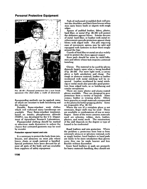
Personal Protective Equipment Pads of cushioned or padded duck will pro tect the shoulders and back from bruises when men carry heavy loads or objects with rough edges Aprons of padded leather, fabric, plastic, hard fiber, or metal (Fig 38-49) will protect the abdomen against blows Similar devices of metal hard fiber, or leather with metal re inforcements provide protection against sharp blows with edged tools For jobs requiring ease of movement, aprons may be split and equipped with fasteners to draw them snugly around the legs Guards of hard fiber or metal are also widely used to protect the shins against impact Knee pads should be worn by mold loftsmen and others whose task requires continual kneeling Fic 38--49 --Personal protection for a wire brush operation--the chest plate is made of aluminum flameproofing methods can be applied, some of which are resistant to both laundering and dry cleaning Durable flame-retardant work clothes which will withstand many launderings are available Their flame-retardant treatment, based on tetrakis phosphonium chloride (THPC), was developed by the U S Depart ment of Agriculture Research Laboratories Flameproofed clothing should be marked or otherwise made distinctive to reduce the chance that untreated garments may be used by mistake Protection against impact and cuts It is necessary to protect the body from cuts, bruises, and abrasions on most jobs where heavy, sharp, or rough material is handled Special protectors have been devised for al most all parts of the body and are available from suppliers of safety equipment Gloves The matenal to be used for gloves depends largely upon what is being handled (Fig 38-50) For most light work, a canvas glove is both satisfactory and cheap For rough or abrasive matenal, leather or leather reinforced with metal stitching will be re quired Leather reinforced by metal stitch ing or metal mesh also provides good protec tion from edged tools, as in butchenng and similar occupations There are many plastic and plastic-coated gloves available They are designed to give protection from a variety of hazards Some surpass leather m weanng ability Others have granules or rough materials incorporated in the plastic for better gripping ability Some are disposable (Fig 38-51) Where the use of a complete glove is not necessary, finger stalls may be used These are available in combinations of one or more fingers Some of the more common materials used are asbestos, rubber, duck, leather, plastics, and metal mesh The construction of the stall depends on the degree or type of hazard to be confronted Hand leathers and arm protectors Where the problem is protection from heat or from extremely abrasive or splintery matenal, such as rough lumber, hand leathers or hand pads are likely to be more satisfactory than gloves since they can be made heavier and less flexible without discomfort Since hand leathers or pads are pnmanly for heavy matenals handling, they should not 1196
refid# 15Ger3G6dRpLMqzojYG18EKRE1 page
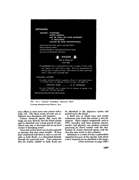
METHANOL DANGER!
refid# z6E5wd9XyBDq4zDJGjeLBaRB1 page
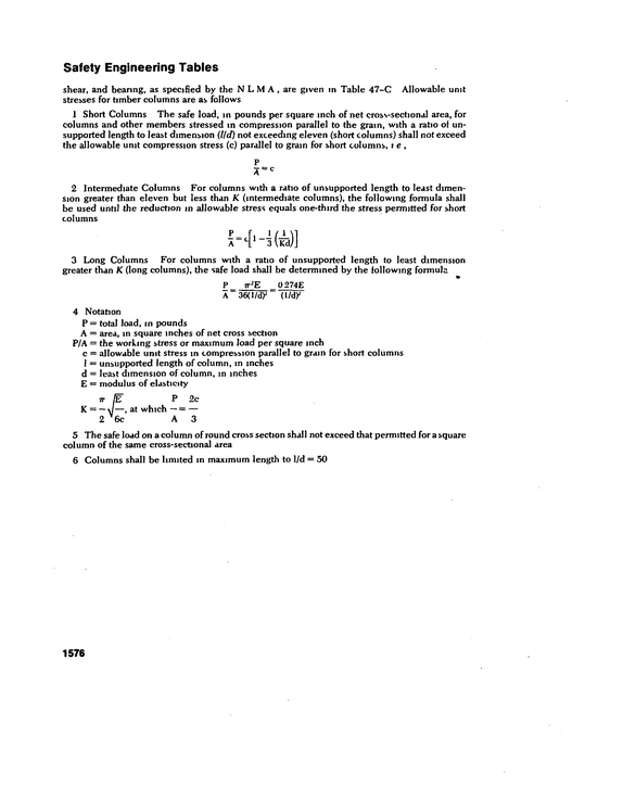
Safety Engineering Tables shear, and bearing, as specified by the NLM A, are given in Table 47-C Allowable unit stresses for timber columns are as follows 1 Short Columns The safe load, in pounds per square inch of net cross-sectional area, for columns and other members stressed in compression parallel to the gram, with a ratio of un supported length to least dimension (Hd) not exceeding eleven (short columns) shall not exceed the allowable unit compression stress (c) parallel to grain for short columns, t e , P A=c 2 Intermediate Columns For columns with a ratio of unsupported length to least dimen sion greater than eleven but less than K (intermediate columns), the following formula shall be used until the reduction in allowable stress equals one-third the stress permitted for short columns 3 Long Columns For columns with a ratio of unsupported length to least dimension greater than K (long columns), the safe load shall be determined by the following formula P 7T*E 0 274E A 36(1/dy (l/dy 4 Notation P = total load, m pounds A = area, m square inches of net cross section P/A = the working stress or maximum load per square inch c = allowable unit stress in compression parallel to grain for short columns 1 = unsupported length of column, m inches d = least dimension of column, m inches E = modulus of elasticity P 2c at which -- = -- A3 5 The safe load on a column of round cross section shall not exceed that permitted for a square column of the same cross-sectional area 6 Columns shall be limited m maximum length to 1/d = 50 1576
refid# evQBjrb62OjQJr95jGnGZz5Ep1 page
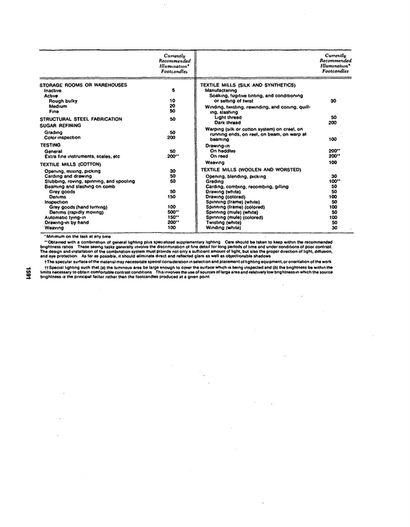
Currently Recommended Illumination* Footcandles Currently Recommended Illumination Footcandles STORAGE ROOMS OR WAREHOUSES Inactive Active Rough bulky Medium Fine STRUCTURAL STEEL FABRICATION SUGAR REFINING Grading Color inspection TESTING General Extra fine instruments, scales, etc TEXTILE MILLS (COTTON) Opening, mixing, picking Carding and drawing Slubbing, roving, spinning, and spooling Beaming and slashing on comb Grey goods Denims Inspection Grey goods (hand turning) Denims (rapidly moving) Automatic tying-in Drawing-in by hand Weaving 5 10 20 50 50 50 200 50 200" 30 50 50 50 150 100 500" 150" 200" 100 TEXTILE MILLS (SILK AND SYNTHETICS) Manufacturing Soaking, fugitive tinting, and conditioning or setting of twist Winding, twisting, rewinding, and coning, quill* mg, slashing Light thread Dark thread Warping (silk or cotton system) on creel, on running ends, on reel, on beam, on warp at beaming Drawing-in On heddles On reed Weaving TEXTILE MILLS (WOOLEN AND WORSTED) Opening, blending, picking Grading Carding, combing, recombing, gillmg Orawing (white) Drawing (colored) Spinning (frame) (white) Spinning (frame) (colored) Spinning (mule) (white) Spinning (mule) (colored) Twisting (white) Winding (white) 30 50 200 100 200" 200" 100 30 100" 50 50 100 50 100 50 100 50 30 Minimum on the task at any lime "Obtained with a combination of general lighting plus specialized supplementary lighting Care should be taken to keep within the recommended brightness ratios These seeing tasks generally involve the discnmination of fine detail tor long periods of time and under conditions of poor contrast The design and installation of the combination system must provide not only a sufficient amount of light, but also the proper direction of light, diffusion, and eye protection As far as possible, it should eliminate direct and reflected glare as well as objectionable shadows tThe specular surface of the matenal may necessitate special consideration in selection and placement of lighting equipment, or onentation of the work ft Special lighting such that (a) the luminous area be large enough to cover the surface which is being inspected and (b) the bnghtness be within the limits necessary to obtain comfortable contrast conditions This involves the use of sources of large area and relatively low bnghtness in which the source brightness is the principal factor rather than the footcandles produced at a given point 1591
refid# ExaJGGBdvQOoO0M99QQ6qp7aL1 page
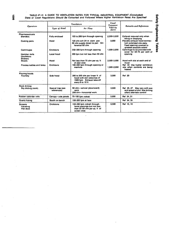
Safety Engineering Tables 1596 TABLE 47-H A GUIDE TO VENTILATION RATES FOR TYPICAL INDUSTRIAL EQUIPMENT (Concluded) State or Local Regulations Should Be Consulted and Followed Where Higher Ventilation Rates Are Specified Operation Pharmaceuticals Blenders Coating pans Centnfuges Hammer mills Oscillators Shakers Mixers Process kettles and tanks Pouring hoods Foundry Rock drilling Dry dnllmg (rock).
refid# qMX2oanE18LNyrK9byGyB5Zk1 page
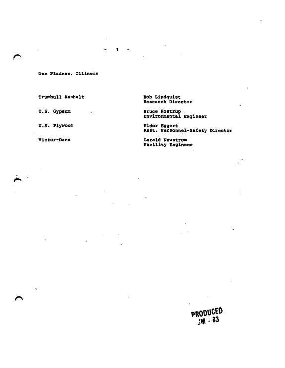
Des Plaines, Illinois Trumbull Asphalt U.S.
refid# JN6B8vMM8x1Nn6b98k9GNdJvv1 page
U.

refid# qv7wk9pyB2d0X5Rgn3bjQ1Zq1 page