Refine
Estimated Years 2000-2009Clear
18,679 results foundRefine Search
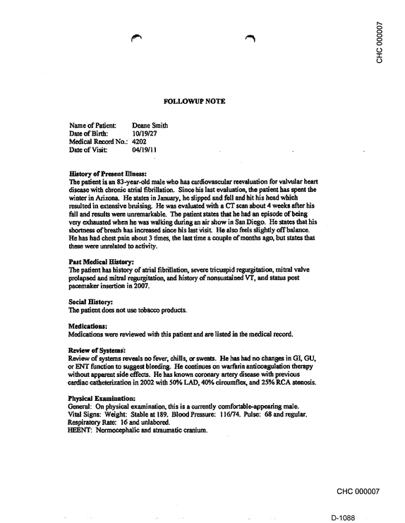
CHC 000007 r> FOLLOWUP NOTE Name of Patient: Deane Smith Date of Birth: 10/19/27 Medical Record No.: 4202 Date of Visit 04/19/11 History of Present Illness: The patient is an 83-year-old male who has cardiovascular reevaluation for valvular heart disease with chronic atrial fibrillation.

refid# YrMe64Y1KZZmvOwZ0dnxg0bzV2 pages
SUPREME COURT OF THE STATE OF NEW YORK FIFTH JUDICIAL DISTRICT .



refid# VJpEoLZ2vD0VraJrrbBX71MGo47 pages
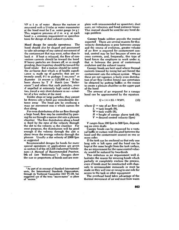
VP is 1 in of water Hence the suction as measured with a U-tube or water manometer at the hood must be 2 in water gauge (wg) This negative pressure of 2 in w g at each hood is a common requirement in specifica tions for design of dust exhaust systems Hood design for specific operations The hood should also be shaped and positioned to take advantage of any natural movement of the contaminant that may exist, rather than to buck it If heat is released, the flow of con vection currents should be toward the hood If heavy particles are thrown off, as in rough grinding, their trajectory should be toward the hood intake But a caution should be noted the air-bome dust which is of health signifi cance is made up of particles that are ex tremely small, 0 1 to perhaps 5 microns in diameter (A micron is 1/25,000 in ) It has been shown by T F Hatch (see "Refer ences") and others that such particles, even if impelled at extremely high initial veloci ties, travel a very short distance m air--a mat ter of a few inches at the most Unlike chips or large particles, they cannot be thrown into a hood any considerable dis tance away The hood acts by confining a mass air movement into it which carries the dust along For even distribution of the air flow through a large hood, flow may be controlled by pass ing the air through a narrow slot into a plenum chamber The flow distribution along a hood is fixed by the ratio of the velocity through the slot to the velocity m the chamber For most purposes, the distribution will be good enough if the velocity through the slot is about twice the average velocity through the plenum Usually a slot velocity of 2000 fpm is suggested Recommended designs for hoods for many special operations or applications are given m section 5 of the ACGIH Industrial Ventila tion--A Manual of Recommended Practice, 9th ed (see "References") Designs show the size or proportions of hoods and are com- 0 As part of its concept of Standard International units, the International Standards Organization, through its Technical Committee ISO TC-20, has suggested use of the term "micro-meter" in place of "micron " plete with recommended air quantities, duct sizes, air velocities and hood entrance losses This manual should be used for any hood de sign problem Canopy hoods seldom provide the control expected There are several reasons for this velocity distribution is poor between canopy and the source of evolution, greater volume of air flow is required for contaminant con trol, control may be lost because of room air cross currents, and, frequently, this type of hood forces the employee to work under it, that is between the point of contaminant evolution and the exhaust source Canopy hoods are best used where thermal currents (caused by rising hot air) funnel the contaminant into the exhaust system Where these are not vigorous, a fairly even distribu tion of air flow (within limits) can sometimes be obtained by putting baffles in the center to create a plenum chamber in the upper part of the hood The amount of air required for a canopy hood can be approximated by the equation Q = 14 x2(L+ W)HV, (13) where Q = rate of air flow (cfm), L -- tank length (ft), W = tank width (ft), H = height of canopy above tank (ft), V = desired control velocity (fpm) V ranges from 100 fpm to 500 fpm, depend ing on cross drafts Canopy hoods can be improved by a verti cal baffle or curtain wall (located between the hood and the contaminant source) on one or more sides If the tank can be enclosed so that only one long side is left open and the hood can be kept at the same height from the tank surface, the air requirement for the same control veloc ity would be reduced by two-thirds This reduction in air requirement well il lustrates the reason for secunng hoods which partially or completely enclose the process, even if hoods must be constructed with chan nels to accommodate monorails or must be made so they will nse or swing to one side for access to the tank or other equipment The overhead hood takes advantage of the thermal movement of air and mist from warm 863
refid# wqod6YkaZgaQ7GqXOJmzrq0p41 page
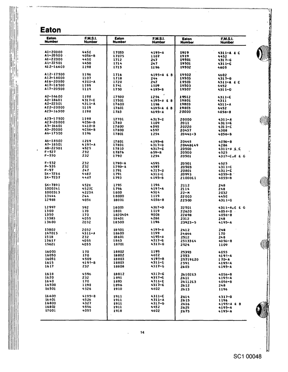
Eaton Eaton Number AI-Z0000 Al-20500 At--2 2000 A1-22 501 A12-166C0 A12-17500 A12--18000 At 6--20500 A17-185O0 A17--20 500 A2-166 00 A2-18601 A2-22501 A22-20000 A23-16500 A23-17500 A23-20000 A3- 16601 A3-20000 A6-17500 A6-18500 A7-18501 A8-22501 F-527 F--530 F- 532 F- 535 F-97 SK --723 6 SK--723 7 SK-7891 1000241 1000313 10444 12988 12997 1300 13 50 13 583 13600 13802 147015 1518 15617 15621 16000 16050 16051 1615 1617 1618 1620 1640 16500 16501 16 600 16 601 16800 16802 17001 F.M.S.I.
refid# wg8G0VBJM1a9YJdLk8kBvV031 page
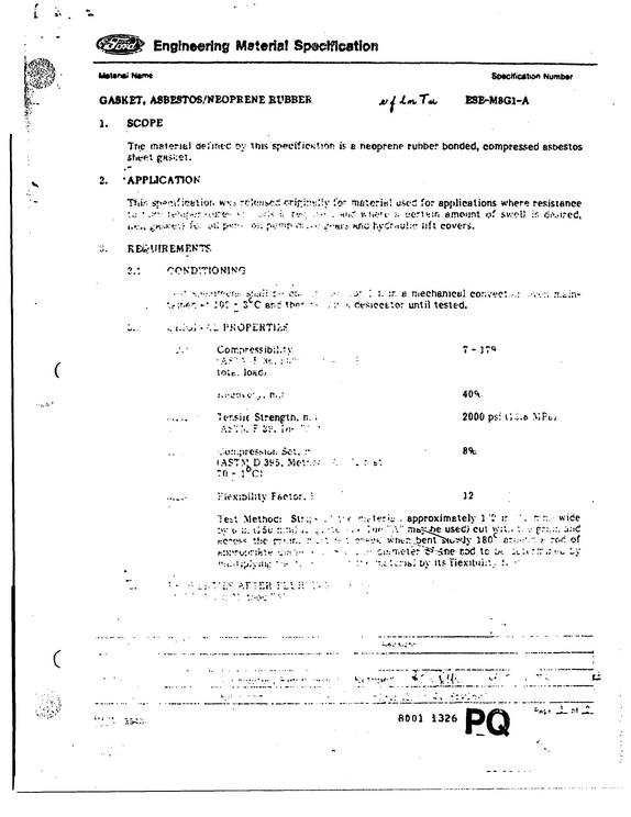
Engineering Material Specification Matanai Name Specification Number GASKET, ASBESTOS/NEOPRENE RUBBER ju j JLn\t T"c ESE-M8G1-A 1.
refid# Em6JyNZk59Loymp9ppYrrnenL1 page
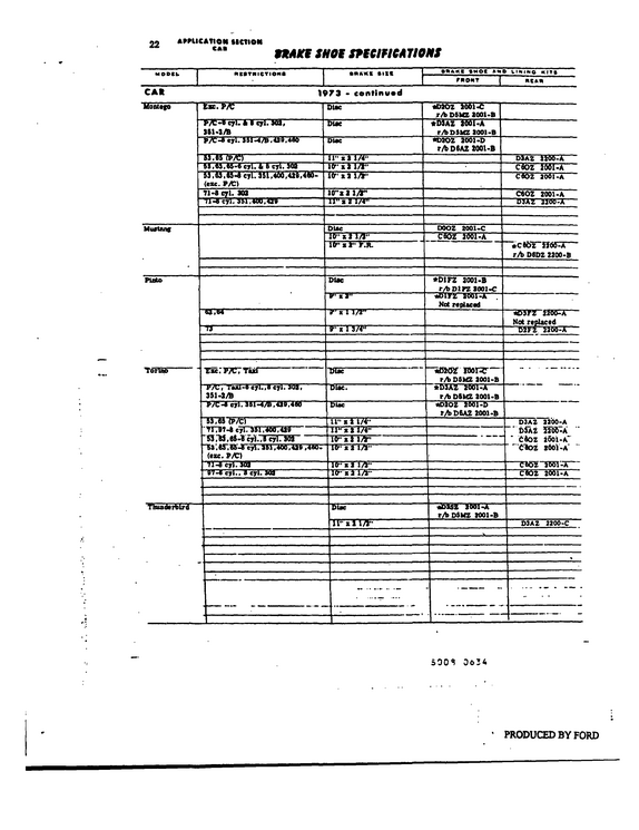
22 APPMCATION MCTION CAB ttAKf SHOE SEEClftCA 71QMS MODCh CAR Monttfo *BTHICYIO IRAKI tlSt 1 >73 - centinw*d rsrm-------------------------------------- DUe P/C-o eyl.
refid# wreLw3wzv03G98K574KEn7v661 page
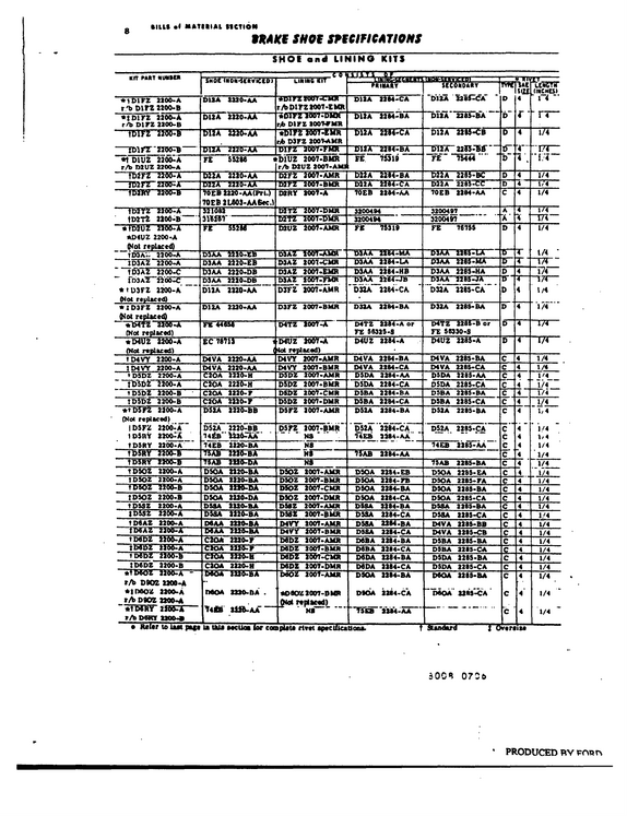
Ill* ( MATIilAl MCTION SHAKE SHOE SPECIFICATIONS SHOE and LINING KITS -------------------- ----------------------------------m ------- LINING kIT LINIttfi-UGHEirn TVDIhllRViClDI psimarv secoaoaaT *1DirZ 2100.A r 'b D1FZ 2200-B D12A 2220-AA *DirZ007-CMH r A>DirZ2007-EMR *imrz 2200-A r/b D1FZ 2200-B D12A 2220-AA ~*D1FZ 2007-DIOf r/b D1PZ 200T-PMR --1MK 2200*6-------- DllA 1220-AA eblfZ 1007-fc Ur r/b D3PZ 2007-AMR ------ DWA "zm-AA-- DTFz 2007-FMR DllA D12A DliA DllA 2264-CA 22M-BA 2284-CA 22B4-BA *t DlUZ 2200-A r/b MUZ 2200-A FE --TB2F2 nw-x-------- D22A H52FZ 2200-X D22A SS2B6 1226- AA 2220-aA *D1UZ 2007-BUR r/b D2UZ 2007-AaUli D2FZ 2007-AMR D2FZ 2007-BMR EE D2lA D22A 75310 2284-BA 2284-CA --nsnsTTowps-- 70EB 2220-AA(Frl.)
refid# ppG7x0XLYX8mj0Q77JvRwORGa1 page
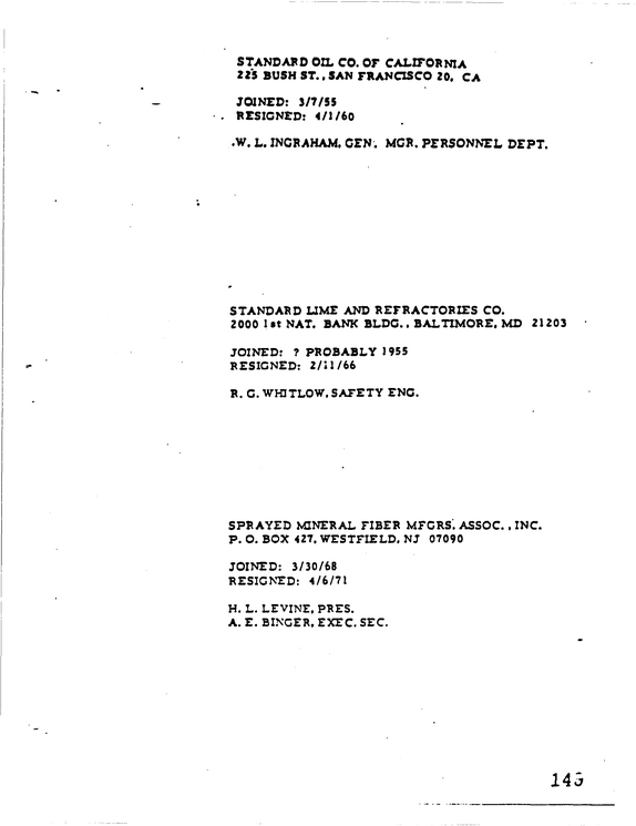
STANDARD OIL CO.
refid# mpb1y1bO9rxQ40M1DZnapabjZ1 page
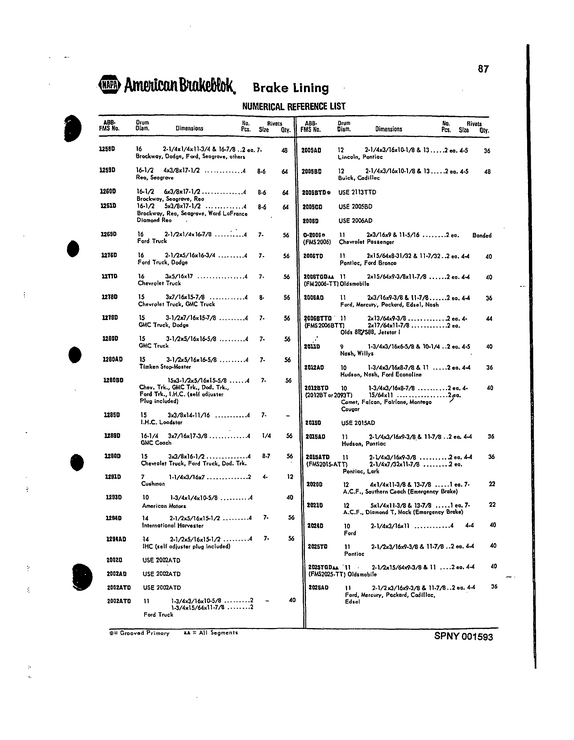
AmMtom&tflkctM, Brake Lining NUMERICAL REFERENCE LIST ABBFMS No.
refid# Gm65jVwB48O61M0gaqpLDkq8n1 page
Page 8 1 San Francisco, California, Friday, July 1, 2005 2 9:10 a.m. - 6:52 p.m. 3 4 DENNIS J.

refid# emaVxG4DLG9BreYeqMdBwxxKG1 page
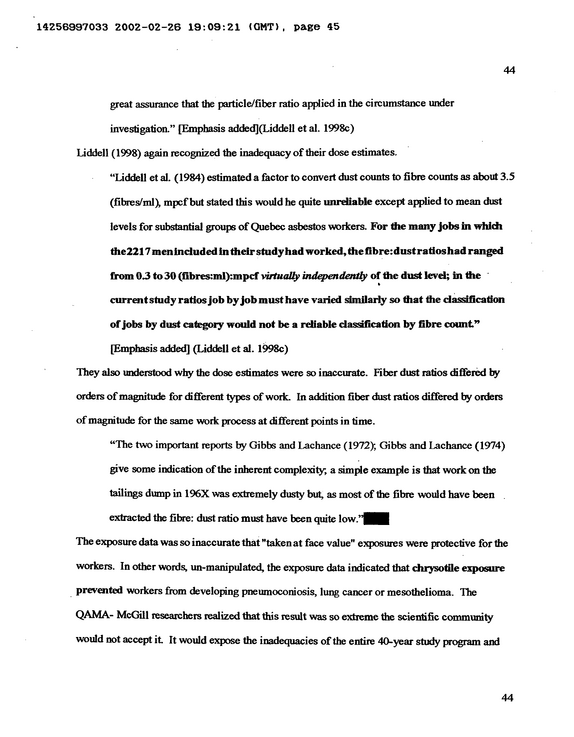
14256997033 2002-02-26 19:09:21 (GMT), page 45 44 great assurance that the particle/fiber ratio applied in the circumstance under investigation."
refid# evjN2beQObYYboOMJMEE2rb3m1 page
14256997033 2002-02-26 19:09:21 (GMT), page 46 45 hundreds of publications.

refid# 717nyz30VvN1eEQ5JO04Zqv6R1 page
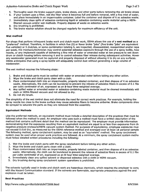
Asbestos-Automotive Brake and Clutch Repair Work Page 3 of 5 5. thoroughly wash the brake support plate, brake shoes, and other parts before removing the old brake shoes 6.
refid# MG9RdMg6yar9JnevMGjM0b3aV1 page
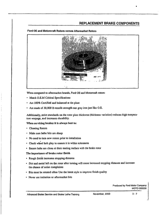
REPLACEMENT BRAKE COMPONENTS Ford OE and Motorcraft Rotors verses Aftermarket Rotors When compared to aftermarket brands, Ford OE and Motorcraft rotors: Match O.E-M Critical Specifications Are 100% Certified and balanced at the plant Are made of 30,000 lb tensile strength cast gray iron just like O.E.
refid# jVO4QmoLgRqNB4wELX883pj21 page
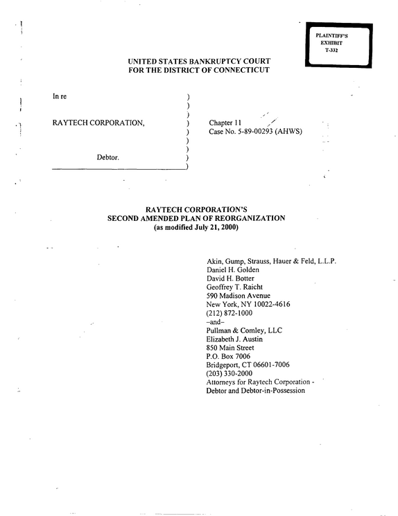
UNITED STATES BANKRUPTCY COURT FOR THE DISTRICT OF CONNECTICUT PLAINTIFF'S EXHIBIT T-332 In re i y RAYTECH CORPORATION, i Debtor. ) ) ) ) Chapter 11 ^ ) Case No. 5-89-00293 (AHWS) ) ) ) ) RAYTECH CORPORATION'S SECOND AMENDED PLAN OF REORGANIZATION (as modified July 21, 2000) Akin, Gump, Strauss, Hauer & Feld, L.L.P.


refid# jN3YoLbbX9xVZ7VZx07bwRaqp179 pages