Refine
Estimated Years 1940-1949Clear
19,188 results foundRefine Search
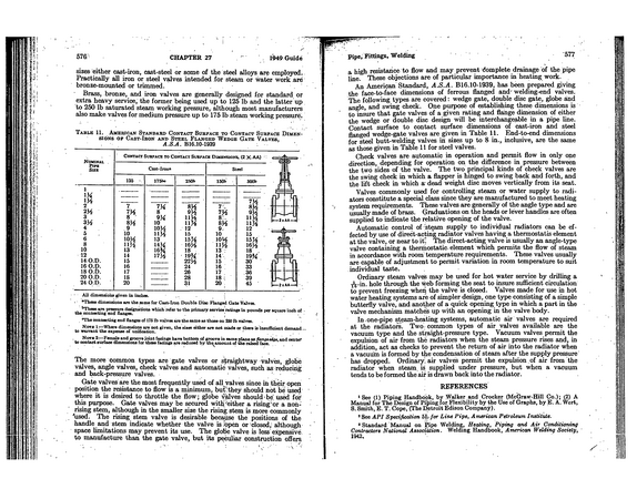
576 CHAPTER 27 ' 1949 Guide j Pipe, Fittings, Welding 577 sizes either cast-iron, cast-steel or some of the steel alloys are employed.
refid# MDYGb1XwJEwEramQxKyQpQ491 page
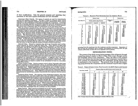
774 CHAPTER 39 1949 Guide of their modifications.
refid# Gz67gm6oeKQ6jnGBj9vVgYOoN1 page
-> .V ' s_* 0.
refid# pe2qVzLERd21ZpeXax0pQojLB19 pages
Confidential ir Mellon Institute of Industrial Research UNIVERSITY OF PllTSBURGH PROGRESS REPORT for the_Keskended__ November 2Z. 194] -INDIISTOT AT.
refid# 2R96BGZkm6QGZw3aKowzg4Lqa1 page
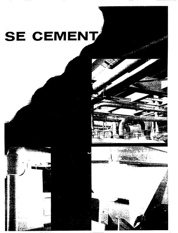
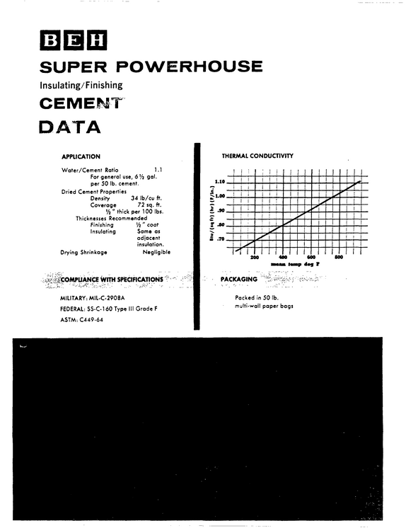
INSULATING CEMENT No. 1 in LOW HEAT LOSS Its Rockwool base contains millions of dead-air cells which retain all their physical properties, contribut ing to low thermal conductivity.

refid# darEeGwqE2D777GnGe6kN2a463 pages
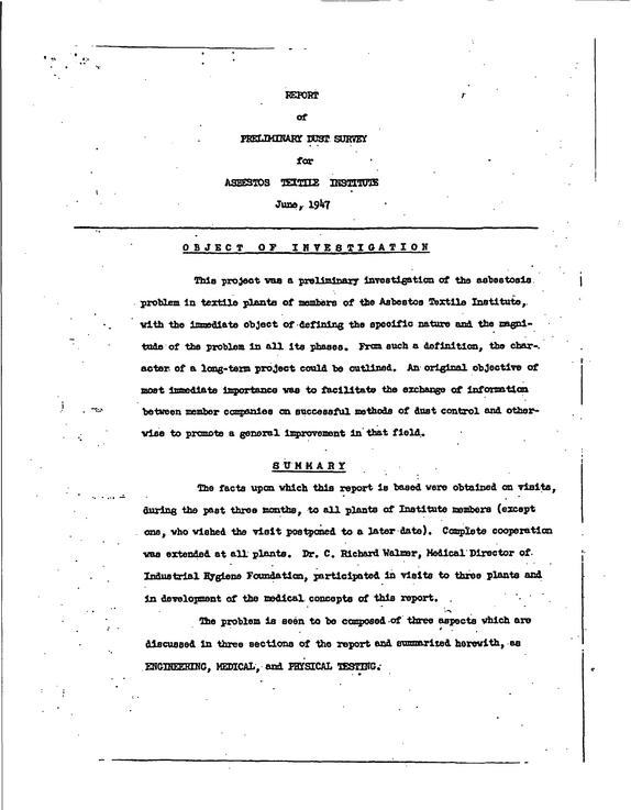
REPORT at PREUKERAKT DUST SURVEY for ASBESTOS TEXTILE MSOTOTE Juno,. 1947 r OBJECT OF IHVESTIPATIOH This project vaa a preliminary Investigation of ths asbestosls. problem In textile plants of members of tbo Asbestos Textile Institute,, with the lmmediata object of-defining the speolflo nature and. the magni tude of tbs problem In all its phases.
refid# zdo0R3EREdy9z1MZ2L8Lowzr71 page
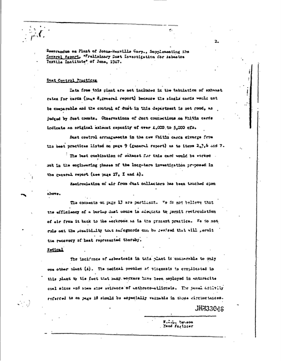
i , on Plant of doeas-^anTllls Corp. , Sa^tl<satlq{ ..the Sadentj. geoort.
refid# YrRed1exe7OOV370ZwEwEnbrk1 page
( \RCH ADVISORY COUNCIL ..................Industrial Hygiene Foundation, Pit .........................................Mellon Institute, Pit . . .
refid# 5krNV4RVo5BzNDb5gY5Ye2vke1 page
TRANSACTIONS of TWELFTH ANNUAL MEETING of INDUSTRIAL HYGIENE FOUNDATION OF AMERICA, INC NOVEMBER 20, 1947
refid# BRYpNLLpY5pdz3bLg0mpGmgRJ1 page
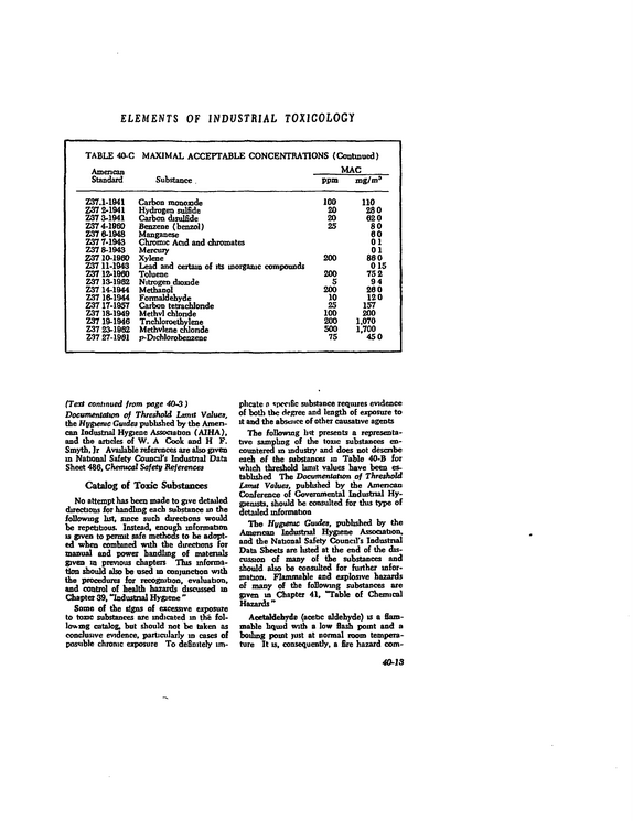
ELEMENTS OF INDUSTRIAL TOXICOLOGY TABLE 40-C MAXIMAL ACCEPTABLE CONCENTRATIONS (Continued) Amencan Standard Substance .
refid# 4OwLDvob50JmDgO2wZVrQzoV1 page
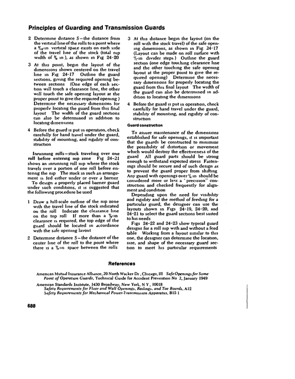
Principles of Guarding and Transmission Guards 2 Determine distance S --the distance from the vertical line of the rolls to a point where a 13/)26-m vertical space exists on each side of the travel line of the stock (total mp width of 3/,, m ), as shown in Fig 24-20 3 At this point, begin the layout of the dimensions shown centered on the travel line m Fig 24-17 Outline the guard sections, giving the required opening be tween sections (One edge of each sec tion will touch a clearance line, the other will touch the safe opening layout at the proper point to give the required opening ) Determine the necessary dimensions for properlv locating the guard from this final layout The width of the guard sections can also be determined in addition to locating dimensions 4 Before the guard is put m operation, check carefully for hand travel under the guard, stability of mounting, and rigidity of con struction Inrunning rolls --stock traveling over one roll before entering nip zone Fig 24-21 shows an inrunning roll nip where the stock travels over a portion of one roll before en tering the nip The stock in such an arrange ment is fed either under or over a barrier To design a properly placed barrier guard under such conditions, it is suggested that the following procedure be used 1 Draw a hil 1-scale outline of the nip zone with the travel line of the stock indicated on the roll Indicate the clearance line on the top roll If more than a '/e-in clearance is required, the top edge of the guard should be located m accordance with the safe opening layout 2 Determine distance S --the distance of the center line of the roll to the point where there is a Vin space between the rolls 3 At this distance begin the layout (on the roll with the stock travel) of the safe open ing dimensions, as shown in Fig 24-17 (Layout can be made on roll surface with `/rin divider steps ) Outline the guard section (one edge touching clearance line and the other touching the safe opening layout at the proper point to give the re quired opening) Determine the neces sary dimensions for properly locating the guard from this final layout The width of the guard can also be determined in ad dition to locating the dimensions 4 Before the guard is put m operation, check carefully for hand travel under the guard, stability of mounting, and rigidity of con struction Guard construction To assure maintenance of the dimensions established for safe openings, it is important that the guards be constructed to minimize the possibility of distortion or movement which would destroy the effectiveness of the guard All guard parts should be strong enough to withstand expected stress Fasten ings should be secure and of such design as to prevent the guard proper from shifting Any guard with openings over'/, m should be considered more or less a ` precision" con struction and checked frequently for align ment and condition Depending upon the need for visibility and rigidity and the method of feeding for a particular guard, the designer can use the layouts shown in Figs 24-19, 24-20, and 24-21 to select the guard sections best suited to his needs Figs 24-22 and 24-23 show typical guard designs for a roll nip with and without a feed table Working from a layout similar to this one, the designer can determine the location, size, and shape of the necessary guard sec tion to meet his particular requirements References American Mutual Insurance Alliance, 20 North Wacker Dr , Chicago, III Safe Openingsfor Some Point of Operation Guards, Technical Guide for Accident Prevention No 2, January 1949 American Standards Institute, 1430 Broadway, New York, N Y, 10018 Safetii Requirements for Floor and Wall Openings, Railings, and Toe Boards, A12 Safety Requirements for Mechanical Power-1 ransmission Apparatus, Bio 1 688
refid# XR1Yzr07Jde3krnNn92eZM9O41 page
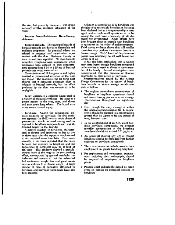
the skin, but primarily because it will almost certainly involve excessive inhalation of the vapor Benzene hexachloride--see Hexachlorocyclohexane.
refid# v6xoG9EK18r6gowE9G9qj1Q161 page
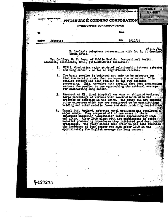
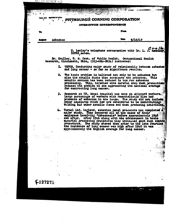
PITTSBURGH CORNING CORPORATIO * INTKR-OmC* COWUWPOWDXWC* #* Asbestos 9/19/17 8.
refid# aB6erD03ODBdB0NDdGZEyKJ0e2 pages
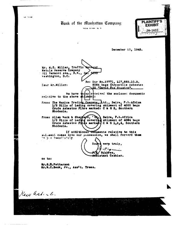
It ' * 4| Sunk nf thr Manhattan (Suutpam; Vf'HK N V PLAINTIFF'S EXHIBIT JM-1403 .frrf'f.l Dtetobtr LO, 1948.
refid# 0LzRVzOJe4E5ZdzdmoRDoZ2Kb1 page
-t a E !
refid# 3O0yqXmX8BqBvb69od47pOLx1 page